
Vertical windmill for fully utilizing bilateral wind energy

A wind energy and windmill technology, applied in the field of fluid kinetic energy receiving devices, can solve problems such as poor utilization and large headwind resistance, and achieve the effects of simplified devices, small headwind resistance, and large windward area

Inactive Publication Date: 2009-12-02
王树然
View PDF5 Cites 4 Cited by
  • Summary
  • Abstract
  • Description
  • Claims
  • Application Information

AI Technical Summary

Problems solved by technology

It can effectively solve the problem that the headwind resistance of various vertical axis windmills is still relatively large, and the wind energy on the other side is not easy to use

Method used


Image

  • Vertical windmill for fully utilizing bilateral wind energy
  • Vertical windmill for fully utilizing bilateral wind energy
  • Vertical windmill for fully utilizing bilateral wind energy

Examples


Embodiment Construction

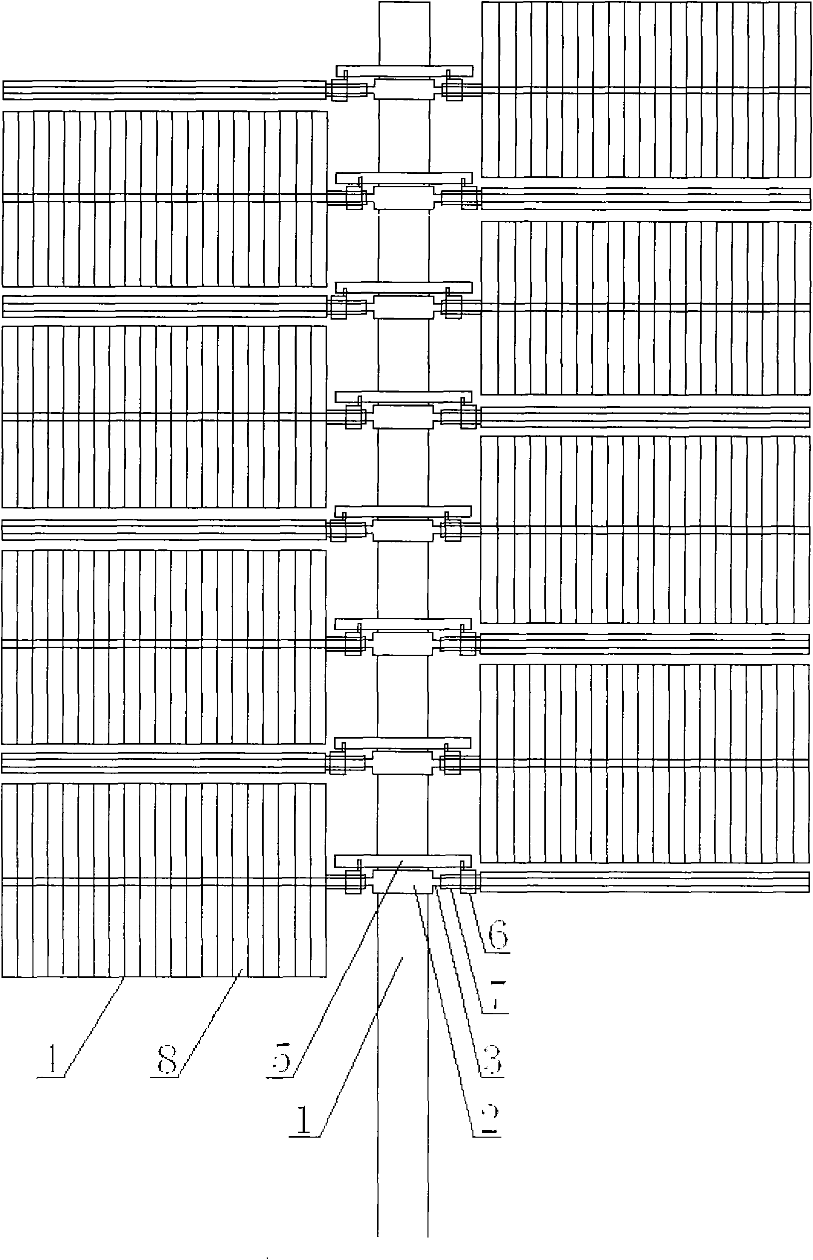
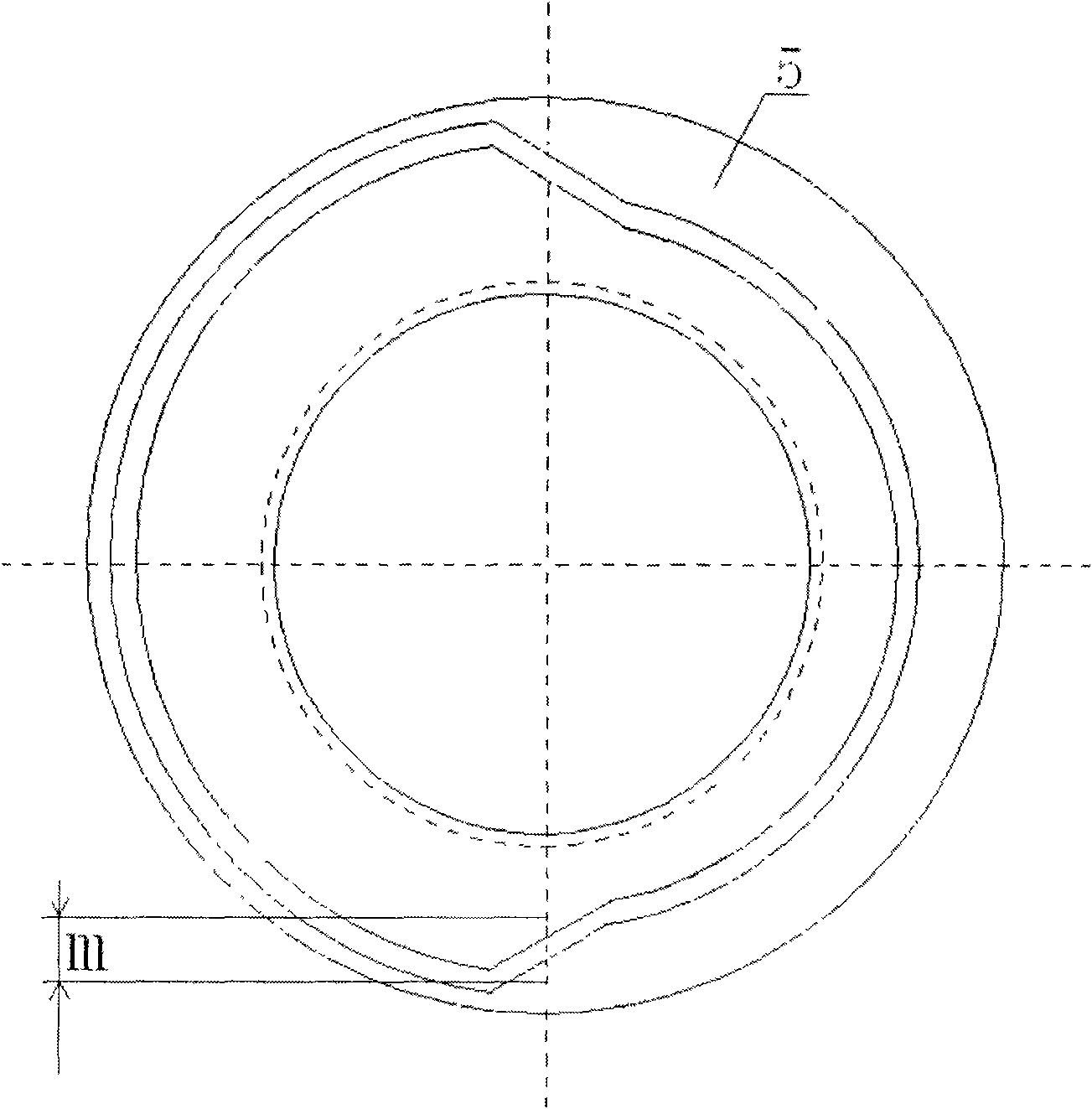
[0015] figure 1 Middle: rotatable large-scale internal tooth gear (2) and rotatable control ring piece (5) are installed layer by layer on the vertical tower (1). Four horizontal force arms (3) are equiangularly connected on the large internal gear (2). Paddle (4), inner-toothed helical wheel (6), and outer-toothed helical wheel (7) are installed on the moment arm (3). Paddle (4) is made up of elastic blade (8) arrangement. The blades are flipped twice a week to maintain the largest area when facing the wind and the least resistance when facing the wind. The rotation directions of the moment arms on the adjacent floors are opposite, so that the wind energy on both sides of the vertical tower can be fully utilized.

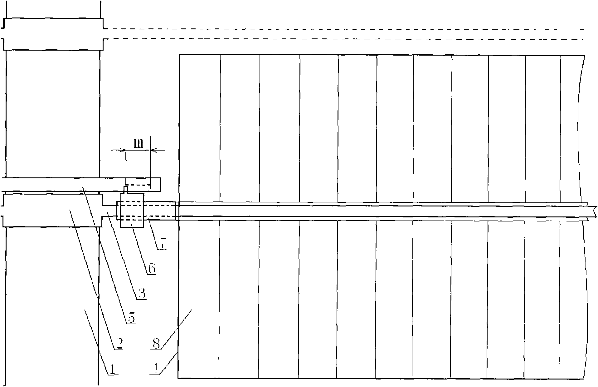
[0016] figure 2 Middle: the paddle (4) (only part is drawn in the figure) is fixedly connected with the external tooth helical wheel (7), and can turn around the moment arm (3), be vertical when facing the wind, and turn to be horizontal when facing the wind. ...


PUM


Abstract

The invention discloses a vertical windmill for fully utilizing bilateral wind energy. A vertical tower is provided with force arms capable of rotating horizontally by layering, and the rotating directions of the force arms of adjacent layers are opposite. Planar paddles can turn over around the force arms, rotate vertically into the wind and rotate horizontally against the wind. Once the force arms rotate for a cycle, the paddles turn over twice, and the turnover is finished by forcing an internal-tooth helical wheel to shift by means of strong rotating thrust of the force arms and interaction of control ring plates so as to push an external-tooth helical wheel to rotate by an angle of 90 degrees. Under the adjustment of a servo tracking device, the windmill can ensure that the paddles turn over at proper time and ensure that the force arms of the adjacent layers are staggered in an angle of 45 degrees when the paddles are in a turnover direction. Elastic blades arranged on the paddles have the wind release function and keep normal running when encountering strong wind. The windmill is free from auxiliary starting during running and can rotate positively or negatively during starting. The vertical windmill has the characteristics of novel structure, simple and convenient manufacture, large windward area, small upwind resistance, full utilization of bilateral wind energy and extremely high wind energy conversion efficiency, and is applicable to large-sized wind generating farms.

Description

Technical field [0001] The invention relates to the technical field of wind power and hydropower, and relates to a fluid kinetic energy receiving device for vertical wind or water power. Background technique [0002] In order to protect the environment and save resources, human beings are intensifying the development of renewable resources such as wind energy, water energy, and solar energy. In particular, improving the development and utilization efficiency of wind energy and water energy is the key goal that people are working hard to overcome. Now commonly used wind power generation device - horizontal axis windmill, there are three blades with small windward area, the direction of motion of the blades is perpendicular to the wind direction, low wind energy utilization rate, high requirements for starting and running wind speed, and the shape, material, weight and strength of the blades High requirements, difficult processing and other issues. While the existing vertical...

Claims


Application Information

Patent Timeline
Patent Type & Authority Applications(China)
IPC IPC(8): F03D3/00F03D11/00F03D3/06F03D7/06
CPCY02E10/72Y02E10/74Y02P70/50
Inventor 王树然
Owner 王树然
Learn More