
Magnetism-gathering transverse magnetic field motor with claw-pole type stator

A transverse magnetic field and magnetism-gathering technology, which is applied to synchronous motors with stationary armatures and rotating magnets, static parts of magnetic circuits, rotating parts of magnetic circuits, etc., can solve complex stator structures and weaken the mechanical strength of motors, etc. problem, to achieve the effect of simple motor structure, reduced core loss, and improved air gap magnetic density

Inactive Publication Date: 2009-11-25
XI AN JIAOTONG UNIV
View PDF0 Cites 9 Cited by
  • Summary
  • Abstract
  • Description
  • Claims
  • Application Information

AI Technical Summary

Problems solved by technology

[0003] Aiming at the technical problem that the air gap structure of the transverse magnetic field permanent magnet motor in the prior art has a high magnetic density and excellent performance, but the stator structure is relatively complicated, which weakens the mechanical strength of the motor, the present invention proposes the following technical solutions:

Method used


Image

  • Magnetism-gathering transverse magnetic field motor with claw-pole type stator
  • Magnetism-gathering transverse magnetic field motor with claw-pole type stator
  • Magnetism-gathering transverse magnetic field motor with claw-pole type stator

Examples


Embodiment Construction

[0020] The present invention will be described below in conjunction with the accompanying drawings.

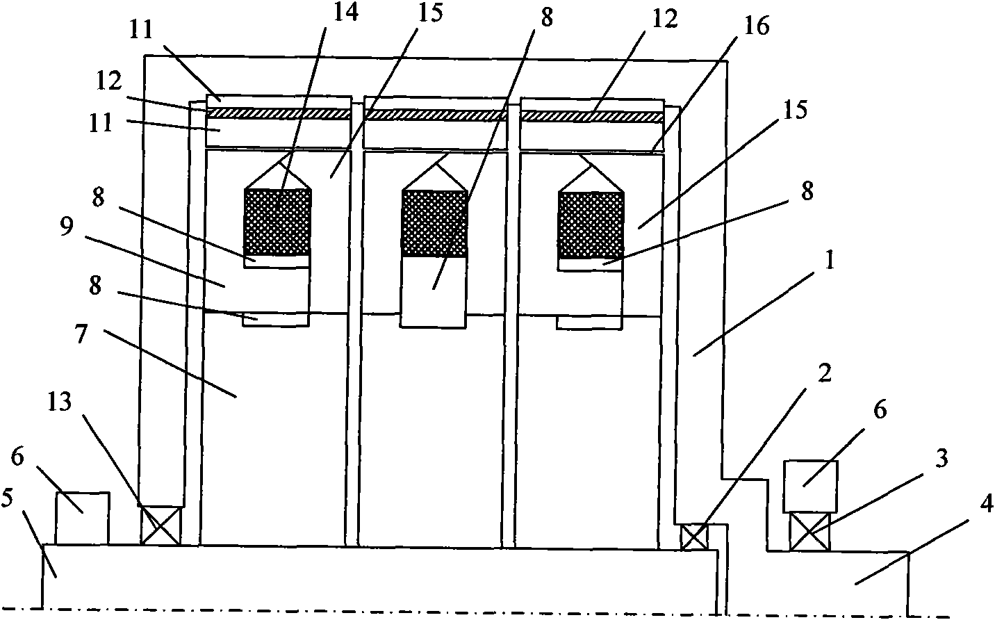
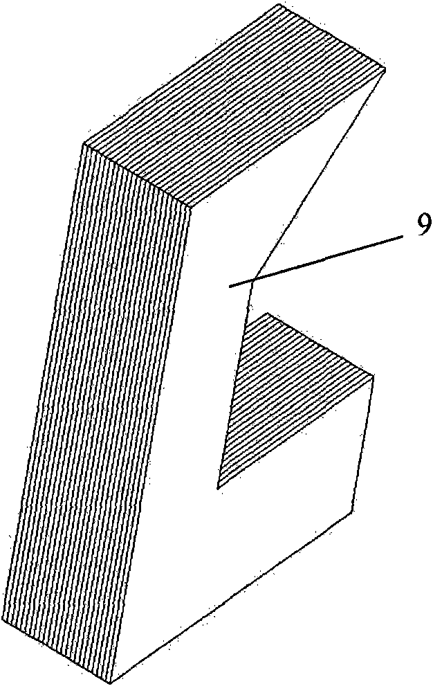
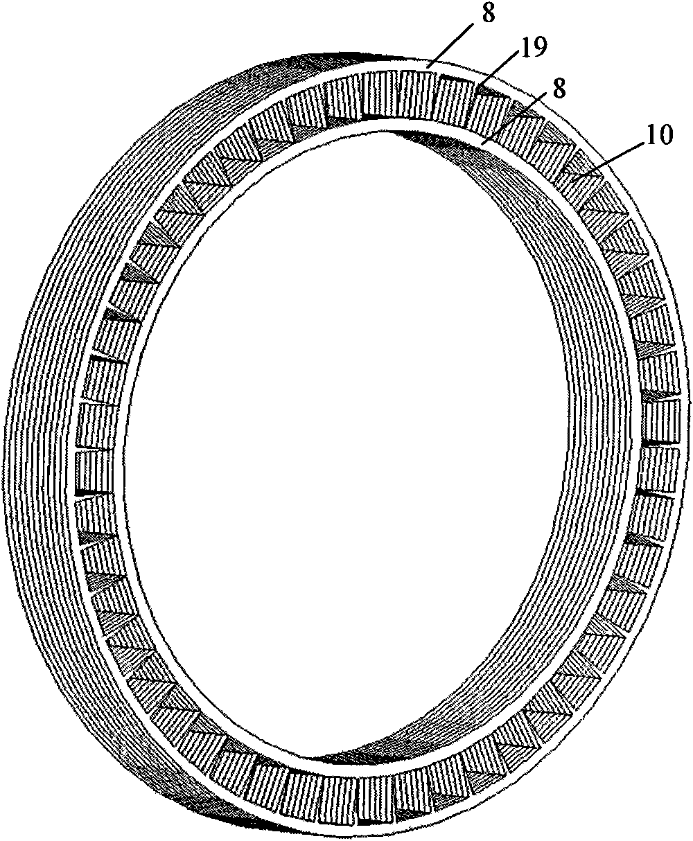
[0021] figure 1 A schematic diagram of the axial structure of the motor. A motor shaft 4 is arranged on the rotor housing 1, a stator fixed shaft 5 is fixed on the motor bracket 6, and three groups of stator brackets 7 are arranged on the fixed shaft 5, each group of stator brackets 7 is provided with an annular stator transition core 8, the stator The transition core 8 is made of silicon steel sheets, and the stacking direction is the axial direction of the motor. The part between the outer edge and the inner edge of the stator transition core 8 is designed to be connected by a V-shaped thin layer 19, so that each stator annular silicon steel sheet is integrated. , which is beneficial to the motor stator processing and the compact and stable stator structure, see image 3 , on the annular stator transition core 8, stator claws 9, 15 are arranged opposite to each other, and ...


PUM


Abstract

The invention belongs to the field of permanent-magnetic motors, and provides a magnetism-gathering transverse magnetic field motor with a claw-pole type stator. The motor comprises a stator fixing shaft and a motor rotating shaft, wherein a shell of the motor and the motor rotating shaft are connected with the stator fixing shaft through a bearing; a stator bracket is arranged on the fixing shaft; a stator core is connected with the stator bracket; the stator core is provided with holes evenly distributed along the circumferential direction; a stator claw tooth is arranged on the stator core; a stator winding is arranged in the middle of the claw tooth; a rotor structure is arranged in an inner cavity of the shell; a rotor core is provided with a radial hole and a circumferential hole; a radial permanent magnet is arranged in the radial hole of the rotor core; a circumferential permanent magnet is arranged in the circumferential square hole of the rotor core; an air gap exists between the stator core and the rotor core; and stator teeth among phases m of the motor differ from each other by 1 / m polar distance. As a rotor of the motor adopts a three-surface magnetism-gathering structure, the motor has the advantages of reducing core loss and increasing the magnetic flux density of the air gap, along with simple structure and easy manufacture.

Description

technical field [0001] The invention belongs to the field of permanent magnet motors, in particular to an outer rotor transverse magnetic field permanent magnet motor of a magnetic concentration rotor. Background technique [0002] The existing transverse magnetic field permanent magnet motor stators mainly adopt U-shape, C-shape and E-shape. The rotor with U-shaped stator structure is divided into two types: flat plate type and magnetic accumulation type: the flat plate type has a simple structure, but the air gap magnetic density is low and the performance is poor; the magnetic accumulation type structure has a higher air gap magnetic density and better performance , but the stator structure generally adopts the structure of inner and outer double stators, and the structure is relatively complicated, which increases the manufacturing cost and difficulty. The rotors with C-shaped and E-shaped stator structures generally adopt a magnetism-concentrating structure: C-shaped a...

Claims


Application Information

Patent Timeline
Patent Type & Authority Applications(China)
IPC IPC(8): H02K21/12H02K1/14H02K1/27
Inventor 赵升吨谢嘉王春辉梁锦涛
Owner XI AN JIAOTONG UNIV
Learn More