Centrifugal switch suitable for motor driving

A centrifugal switch, motor-driven technology, used in electrical switches, motor generators/starters, circuits, etc., can solve the problems of unstable opening and closing of contacts, large impact force, easy damage, etc., to improve convenience, The effect of improving the service life and improving the strength

Inactive Publication Date: 2009-11-25
NINGBO ZHENHAI MICRO ELECTRIC MOTORS FACTORY
View PDF1 Cites 3 Cited by
  • Summary
  • Abstract
  • Description
  • Claims
  • Application Information

AI Technical Summary

Problems solved by technology

This design uses the sleeve to slide up and down to control the opening and closing operation of the lower contact. Since the opening and closing method ado

Method used


Image

  • Centrifugal switch suitable for motor driving
  • Centrifugal switch suitable for motor driving
  • Centrifugal switch suitable for motor driving

Examples


Embodiment Construction

[0022] The present invention will be further described below in conjunction with the embodiments of the accompanying drawings.

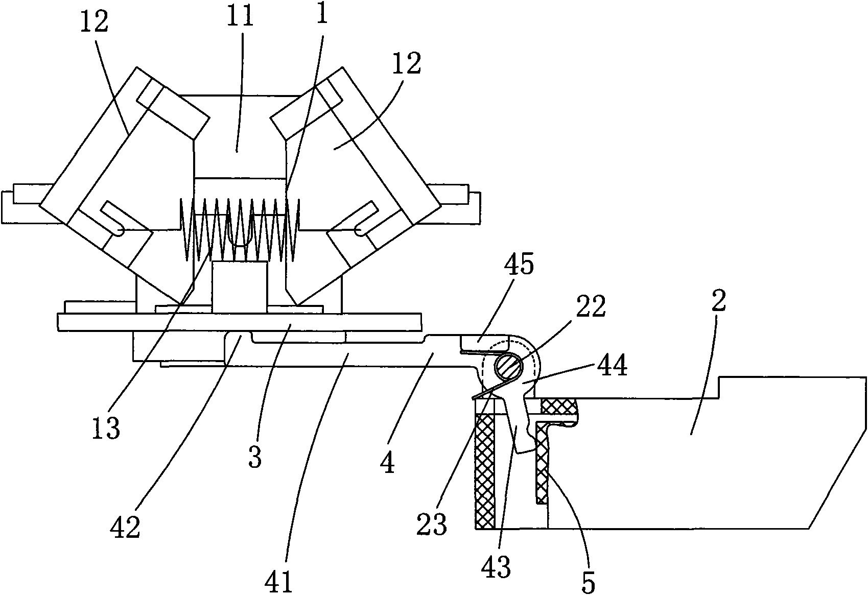
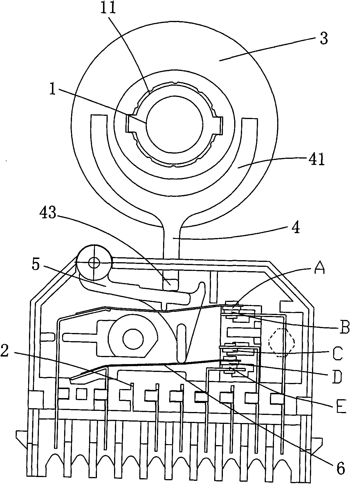
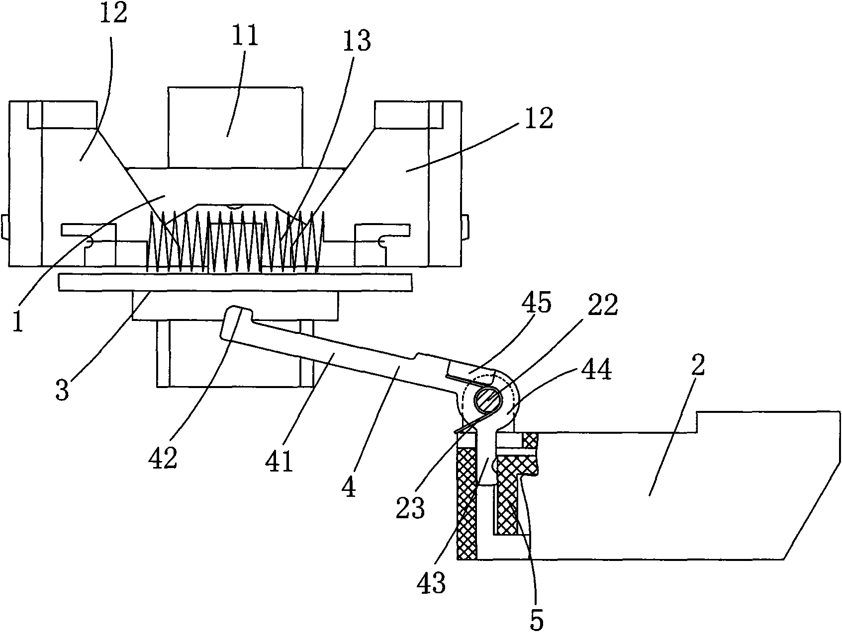
[0023] Such as figure 1 , figure 2 As shown, a centrifugal switch suitable for motor drive consists of two parts: the centrifuge 1 and the wire box body 2 . The centrifuge 1 is installed on the rotating shaft of the motor, and the wire box body 2 is installed on the end cover of the motor.

[0024] The structure of a general centrifuge 1 includes a drive seat 11 that is plugged and matched with the motor shaft. The upper cross arms of the drive seat 11 are symmetrically hung with counterweights 12, and tension springs 13 are hung between the counterweights 12. The tension springs 13 control The counterweight body 12 leans inward against the cage; and the bottom side of the counterweight body 12 is hooked to both sides of the sliding sleeve 3; as the rotation speed of the motor increases, the counterweight body 12 overcomes the centrifugal force of...


PUM


Abstract

A centrifugal switch suitable for motor driving comprises a centrifuge and a wire box body; the centrifuge is set with an axially flexible sliding bushing glidingly matched with a shaft; the wire box body is provided with a contact pole piece set in which clutching of contacts is controlled by front end of a movable rod which is rotatably matched with the wire box body; the centrifugal switch further includes a toggle rod whose middle part is rotatably matched with one side at bottom of the wire box body and is reset by a torque spring; front end of the toggle rod contacts bottom end face of the sliding bushing, and the toggle rod rotates under control of the sliding bushing; further, tail end of the toggle rod is collided with the movable rod. This invention achieves functions as follows: it ensures stable operation of the movable rod since end face of the sliding bushing is regarded as working surface for switching contacts; it simplifies structure of the centrifugal switch and enhances strength of the toggle rod in adoption of the integrative toggle rod, and further prolongs service life of the whole centrifugal switch; further, it reduces complexity of installment and enhances convenience for daily maintenance since the integrative toggle rod is adopted.

Description

technical field [0001] The invention relates to a centrifugal switch, in particular to a motor-driven centrifugal switch. Background technique [0002] Existing washing machines and dry-cleaning machines are equipped with centrifugal switches, which are mainly used for motor start-up and high-speed switching. The main structure of the centrifugal switch adopts a centrifuge and a wiring conversion box; one end of the centrifuge is equipped with an axially sliding control panel, the wiring conversion box is equipped with a conversion contact, and the outer swing of the wiring conversion box has a movable rod, which is controlled by the movable rod. The different changes of the conversion contacts, and the swing of the movable rod is driven by the control disk; according to the existing structure, the contact area between the movable rod and the control disk lies on the outer radial circle of the control disk, because the contact of the outer radial circle After all, the area ...

Claims


Application Information

Patent Timeline
IPC IPC(8): H01H35/10H02P1/16
Inventor 鲁文龙
Owner NINGBO ZHENHAI MICRO ELECTRIC MOTORS FACTORY
Why Eureka
Try Eureka