Crane Swing Suspension System

A suspension system and swing-type technology, applied in the direction of cranes, suspensions, elastic suspensions, etc., can solve the problems of large space occupation, large size, and reduced power performance of the whole machine, so as to achieve low manufacturing cost and strong bearing capacity , The effect of ensuring comfort

Inactive Publication Date: 2011-12-28
四川长起起重设备有限公司
View PDF1 Cites 4 Cited by
  • Summary
  • Abstract
  • Description
  • Claims
  • Application Information

AI Technical Summary

Problems solved by technology

The use of traditional leaf springs, coil springs or oil-gas springs will make the components of the suspension system large in size, high in manufacturing costs, and occupy a large space, which cannot be realized in structural design.
However, if the front and rear suspensions are fully rigidly connected, it will result in:
[0003] (1) The suspension system loses the shock absorption and buffering functions, and the ride and operation comfort of the whole machine is poor;
[0004] (2) When the whole machine is running and working on uneven roads, a single wheel will appear in the air, resulting in deterioration of wheel load distribution, damage to related components, and at the same time reducing the adhesion performance of the whole machine, causing engine power loss and reducing the power performance of the whole machine;
[0005] (3) When the whole machine is working on a sloped site (driving with load and working without outriggers), the deviation of the center of gravity of the whole machine will lead to poor stability of the whole machine and reduce the lifting capacity of the whole machine
Although the cooperation of the main and auxiliary springs can solve the problem of no-load and load-carrying of light-duty trucks, because it still relies on springs as a replacement link for the suspension, it still needs huge springs for heavy loads, so this structure does not It cannot solve the problem of heavy-duty vehicles, especially cranes, and the change of unloaded loads

Method used


Image

  • Crane Swing Suspension System
  • Crane Swing Suspension System
  • Crane Swing Suspension System

Examples


Embodiment Construction

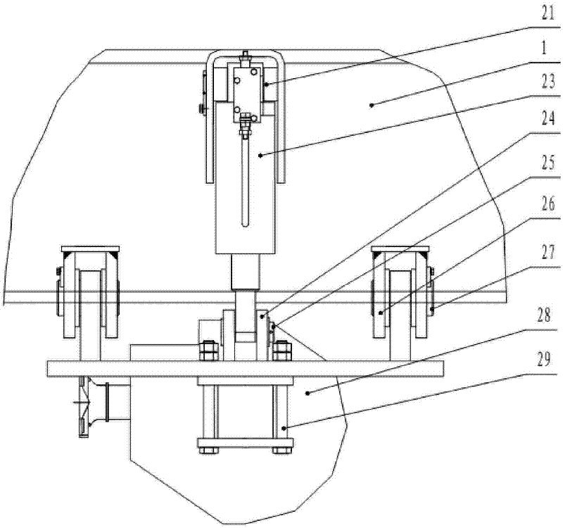
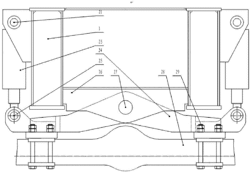
[0025] Specific embodiments of the present invention, such as figure 1 Shown, a kind of crane swing type suspension system, comprises the underframe 1 of vehicle, is equipped with front suspension and rear suspension 4 on underframe 1, and front suspension comprises the front suspension bracket that is welded on the underframe 1 Seat 2, front suspension bearing 2 are rigidly connected together with front drive axle 5 through shock absorbing pad 3 and connecting bolt 4 and are fixed together. Such as figure 2 , 3 As shown, the rear suspension 24 is hinged on the hinged support 26 on the underframe 1 through a pin shaft 27, and the direction of the pin shaft 27 is perpendicular to the direction of the wheel shaft. Two locking oil cylinders 23 are symmetrically arranged on both sides of pin shaft 27, and are installed between rear suspension 24 and underframe 1, preferably, as figure 2 , 3 As shown, the cylinder body of the locking cylinder 23 is hinged to the underframe 1 ...


PUM


Abstract

The invention discloses a crane swing suspension system, which comprises a vehicle chassis and front and rear suspensions, and is characterized in that the front suspension comprises a front suspension support fixed on the chassis, and the front suspension support It is rigidly connected with the front drive axle, and the rear suspension is hinged on the chassis through a pin shaft. The direction of the pin shaft is perpendicular to the direction of the wheel shaft. Two locking cylinders are symmetrically arranged on both sides of the pin shaft, and are installed on the rear suspension and the chassis Between the rod chamber and the rodless chamber of the locking cylinder, a control valve group controlled by an electronic control system is arranged on the connecting pipeline, and the rear suspension is rigidly connected with the rear drive axle. The crane swing suspension system of the present invention has the characteristics of being able to flexibly adapt to the load-bearing changes of the crane on different roads and industrial and mining environments, and has the characteristics of simple structure, strong bearing capacity, convenient layout, and low manufacturing cost.

Description

technical field [0001] The invention relates to a heavy-duty vehicle, especially a suspension system of a crane. Background technique [0002] When the crane is in a working condition such as driving with load, the axle load of the whole machine is transferred, and the single axle load can reach 80,000-90,000kg. The use of traditional leaf springs, coil springs or oil-pneumatic springs will make the components of the suspension system huge in size, high in manufacturing costs, and occupy a large space, which cannot be realized in structural design. However, if the front and rear suspensions are fully rigidly connected, it will result in: [0003] (1) The suspension system loses the shock absorption and buffering functions, and the ride and operation comfort of the whole machine is poor; [0004] (2) When the whole machine is driving and working on uneven roads, a single wheel will appear in the air, resulting in deterioration of wheel load distribution, damage to related c...

Claims


Application Information

Patent Timeline
Patent Type & Authority Patents(China)
IPC IPC(8): B66C23/62B60G13/00B60G17/00
Inventor 韩应奎陈志斌王美成何清荣陈殿春
Owner 四川长起起重设备有限公司
Why Eureka
Try Eureka