Processing box

A technology for processing cartridges and sliding elements, which can be used in electrography, optics, instruments, etc., to solve problems such as toner leakage

Inactive Publication Date: 2009-11-18
ZHUHAI SEINE TECH CO LTD
View PDF0 Cites 9 Cited by
  • Summary
  • Abstract
  • Description
  • Claims
  • Application Information

AI Technical Summary

Problems solved by technology

[0007] The invention provides a processing box to solve the technical problem that the existing processing box has a gap between the sliding component and the powder outlet, so that the carbon powder is easy to leak out from the sliding component

Method used


Image

  • Processing box
  • Processing box
  • Processing box

Examples


Embodiment Construction

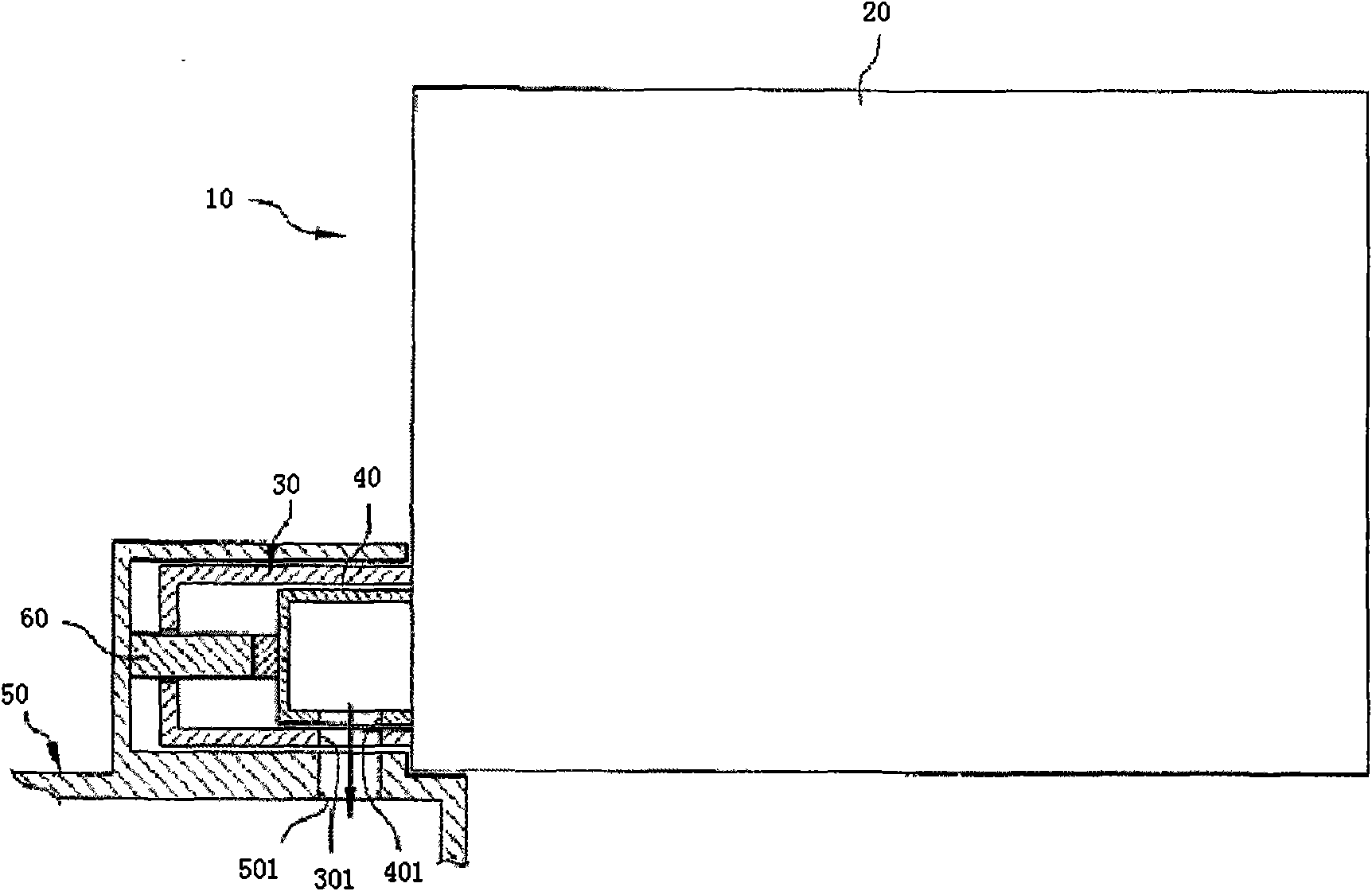
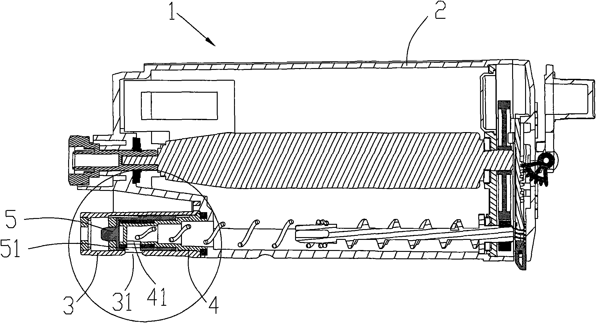
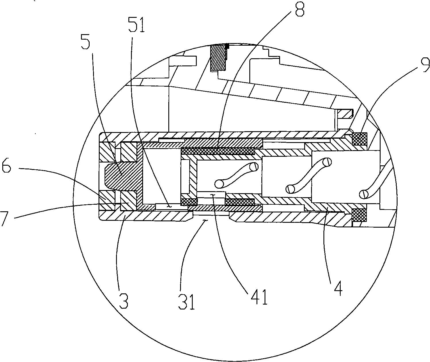
[0021] Such as figure 2 As shown, the process box 1 includes: a powder cylinder 2, a powder outlet part 3, an internal element 4 and a sliding element 5, the powder cylinder 2 is in the shape of a cylinder, and carbon powder is stored therein; the carbon powder can be transported to the powder outlet part 3 .

[0022] The powder outlet part 3 is arranged at the front end of the powder cylinder 2, and cooperates with corresponding components on the electrophotographic imaging system to provide carbon powder for the electrophotographic imaging system. There is a powder outlet 31 on the powder outlet part 3 .

[0023] There is an internal element 4 inside the powder outlet part 3, the internal element 4 is fixed inside the powder outlet part 3, and forms a certain space with the powder outlet part 3, and an internal powder feeding port 41 is arranged on the internal element 4.

[0024] Internal powder feeding port 41 such as figure 2 set on the circumferential surface of the ...


PUM


Abstract

The invention discloses a processing box. The processing box comprises a powder cylinder for containing carbon powder, a sliding element which can freely slide in the powder cylinder and a sliding element retaining mechanism which leads the sliding element to close a powder outlet at non-using state, wherein a powder outlet part is arranged on the powder cylinder, the powder outlet is formed on the powder outlet part, when in the non-using state, the sliding element closes the powder outlet under the action of the sliding element retaining mechanism; when in using state, the sliding element is moved under the action of external force for opening the powder outlet, an internal element with an internal powder feed inlet is further arranged in the powder outlet part, the internal element and the powder outlet part form a certain space, the sliding element can slide in the space formed by the powder outlet part and the internal element, and the internal powder feed inlet of the internal element is butt-jointed with the powder outlet. As the processing box increases the internal element for re-sealing, the carbon powder can not be leaked out, thereby solving the technical problem that the carbon powder is easy to leak from the sliding element due to the existence of a gap between the sliding element and the powder part of the prior processing box.

Description

technical field [0001] The invention relates to an electrophotographic imaging system, such as a laser printer, a copier, a facsimile machine, etc., in particular to a process box of an electrophotographic imaging system. Background technique [0002] In the prior art, there is provided a process cartridge detachable from the electrophotographic imaging system, and when the process cartridge is mounted on the electrophotographic imaging system, the process cartridge can provide toner for the electrophotographic imaging system. [0003] Such as figure 1 As shown, a process cartridge 10 includes: a powder cartridge 20 storing carbon powder in the powder cartridge 20; a powder outlet part 30 arranged at the front end of the powder cartridge 20; a sliding element 40 in the powder outlet part 30. There is a powder outlet 301 on the powder outlet part 30 , and a powder feeding outlet 401 on the sliding element 40 . [0004] When the process box 10 was installed on the electropho...

Claims


Application Information

Patent Timeline
IPC IPC(8): G03G21/18
CPCG03G2215/068G03G2215/0692G03G15/0832G03G15/0875G03G15/0886G03G15/0865G03G15/0855
Inventor 吴连俊刘金莲彭庆菲
Owner ZHUHAI SEINE TECH CO LTD
Why Eureka
Try Eureka