Lens drive device

A lens drive device and lens technology, which is applied in the field of photography, can solve the problems that the quality of the lens frame has a great relationship with the motion response ability, the motion response ability declines, and the module cannot work normally, etc., achieving high positioning accuracy, easy control, and consistency Good results

Inactive Publication Date: 2012-11-07
JOHNSON ELECTRIC SHENZHEN
View PDF2 Cites 1 Cited by
  • Summary
  • Abstract
  • Description
  • Claims
  • Application Information

AI Technical Summary

Problems solved by technology

[0005] Although this kind of inertial drive scheme is simple in structure, it has the following disadvantages: in order to ensure the stroke, the drive rod needs to have a certain length. Response ability decreases; this kind of motion response ability has a great relationship with the quality of the lens holder; in addition, the piezoelectric ceramic and the driving rod are connected by adhesive, and the bonding strength is affected by the length of the rod, the cross-sectional area of ​​the rod and the quality. Influence, when the mobile phone falls, the driving rod is easy to fall off from the piezoelectric ceramic, causing the whole module to fail to work normally

Method used


Image

  • Lens drive device
  • Lens drive device
  • Lens drive device

Examples


Embodiment Construction

[0030] In order to make the technical problems, technical solutions and beneficial effects to be solved by the present invention clearer, the present invention will be further described in detail below in conjunction with the accompanying drawings and embodiments. It should be understood that the specific embodiments described here are only used to explain the present invention, not to limit the present invention.

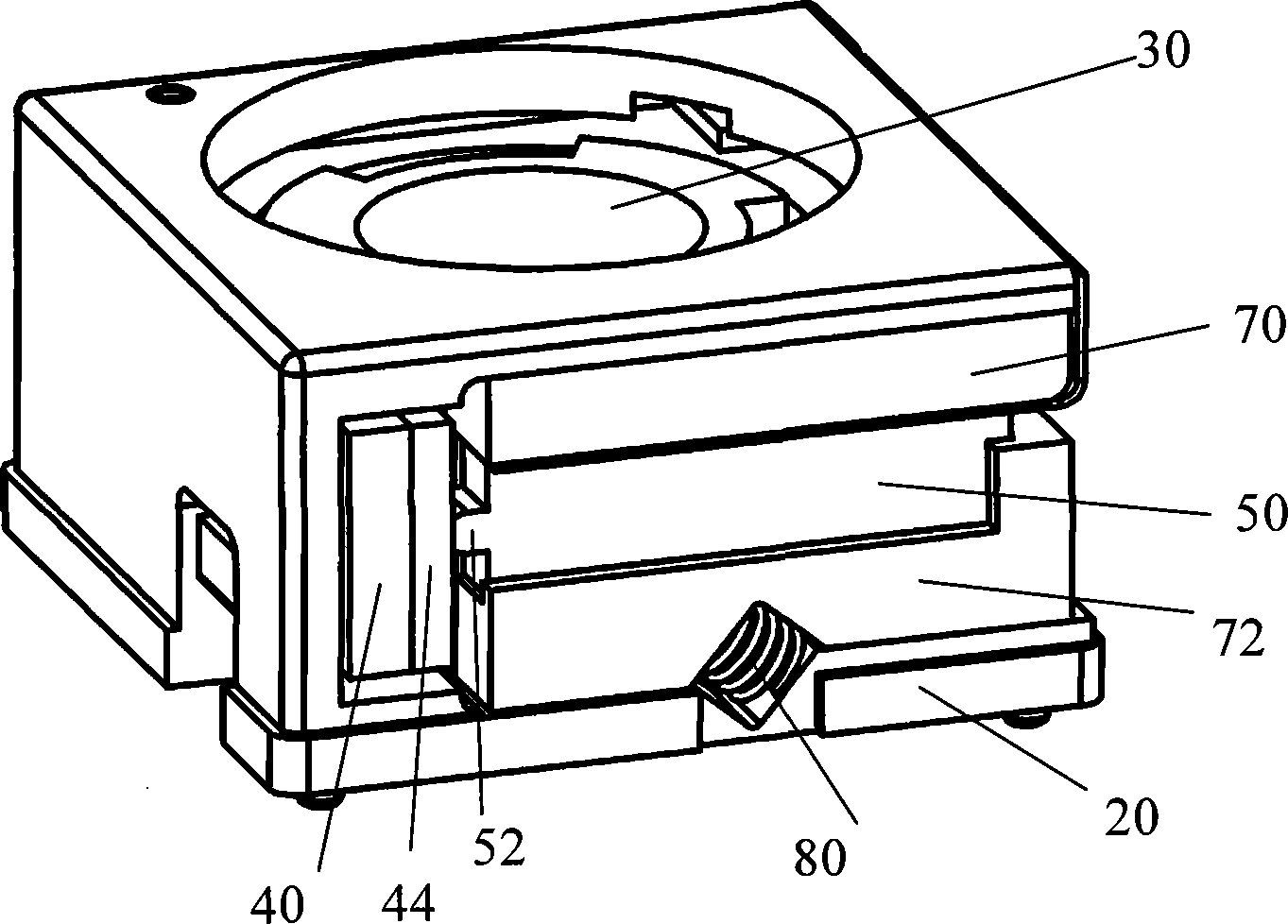
[0031] figure 1 It is a schematic diagram of the assembly structure of the lens driving device provided by an embodiment of the present invention. figure 2 It is a schematic diagram of the lens driving device provided by an embodiment of the present invention without the housing. image 3 It is an exploded diagram of a lens driving device provided by an embodiment of the present invention.

[0032] Such as Figure 1 to Figure 3 As shown, the lens driving device according to an embodiment of the present invention includes a base 20, a lens frame 40 for installi...


PUM


Abstract

The invention provides a lens drive device which comprises a base, a lens frame, a guide mechanism installed between the base and the lens frame, an anti-rotary mechanism installed between the base and the lens frame and a piezoelectric motor with a motor head installed on the base through a motor seat, wherein the lens frame can slide relative to the base along the optical axis direction of a lens. A friction resisting part is arranged on the lens frame near the motor head, and a pretightening component is arranged between the motor seat and the base and supports against the motor seat, thereby certain pre-tightening force is generated between the motor seat and the friction resisting part. When the piezoelectric motor is excited, the motor head drives the lens frame to move along the optical axis direction of the lens. In the lens drive device, the motor head of the piezoelectric motor directly drives the lens frame, and the stroke and the position of the lens frame cannot influencethe response capability of the lens frame to the vibration of the piezoelectric motor; compared with the prior lens drive device driven by a voice coil motor, the invention has stronger anti-droppingability as well as fast response and location speed, and is convenient to pick up an image; the invention can realize self-locking by making use of the friction, and more saves the electricity.

Description

【Technical field】 [0001] The invention relates to the technical field of imaging, in particular to a lens driving device. 【Background technique】 [0002] With the popularization of mobile phones and the diversification of their functions, mobile phones with auto-focus cameras have increasingly broad market prospects. The existing auto-focus mobile phone lens driving devices on the market usually use a voice coil motor to drive the lens, which is characterized in that the electromagnetic force is balanced with the elastic force, and the position of the lens is changed by changing the driving current. The lens device driven by the voice coil motor needs to balance the elastic force and the mechanical oscillation time is long, so the response speed is slow, the focus wait time is long, and it cannot continue to focus during the shooting process; it needs to input current when maintaining the lens position; and, because Using shrapnel to support the lens, the impact force of th...

Claims


Application Information

Patent Timeline
Patent Type & Authority Patents(China)
IPC IPC(8): G02B7/04G02B7/09H02N2/00
Inventor 石斌李红李兴全张勇刚
Owner JOHNSON ELECTRIC SHENZHEN
Why Eureka
Try Eureka