New technique for manufacturing high alloy steel seamless pipe with heavy calibre by adopting pilger mill

A high-alloy steel, seamless tube technology, applied in the direction of manufacturing tools, metal rolling, metal processing equipment, etc., can solve the problems of dimensional accuracy, surface quality, high cost, long process, etc. Equipment investment and operating costs, as well as the effect of floor space, reduced workload, and short process flow

Inactive Publication Date: 2009-11-18
北京蓝海科融新技术有限公司
View PDF1 Cites 14 Cited by
  • Summary
  • Abstract
  • Description
  • Claims
  • Application Information

AI Technical Summary

Benefits of technology

Inventions described earlier have several technical benefits: they allow for faster production without requiring expensive materials or having complex operations, while still maintaining good physical characteristics like strength and durability over longer periods of service life. Additionally, these methods involve no steps needed during the fabrication process itself, reducing labor requirements and improving efficiency. Overall, these improvements help make pipes made from them more cost-effective and efficient compared to traditional ways.

Problems solved by technology

The technical problem addressed in this patents relates to developing improved metallography techniques for efficiently producing very thin weldability materials without compromising their mechanical property qualities due to impurities contained within them. Existing solutions require multiples of coolings and tools, leading to longer times needed for finishing operations compared to smaller ones.

Method used


Image

  • New technique for manufacturing high alloy steel seamless pipe with heavy calibre by adopting pilger mill
  • New technique for manufacturing high alloy steel seamless pipe with heavy calibre by adopting pilger mill
  • New technique for manufacturing high alloy steel seamless pipe with heavy calibre by adopting pilger mill

Examples


Embodiment Construction

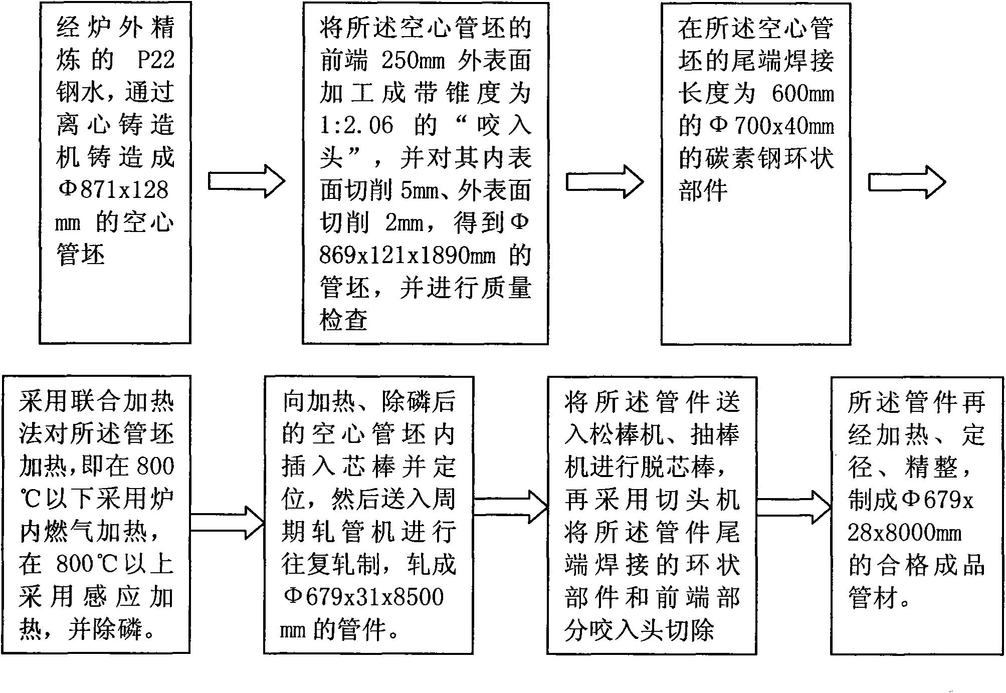
[0042] Such as image 3 Shown is a process flow diagram of an embodiment of the present invention, which specifically includes the following process steps:

[0043] In the first step, the high-pressure boiler tube refined outside the furnace is centrifugally cast with P22 molten steel into a hollow tube blank of Φ871x128mm through a centrifugal casting machine. In this step, the molten steel refined outside the furnace is the same as the prior art, and will not be repeated here; the centrifugal casting is carried out on a horizontal centrifugal casting machine with an angle of 0 degrees between the rotation axis of the mold and the horizontal. The cast hollow tube blank is a hollow tube blank with equal wall thickness and transparent ends. Using the centrifugal casting machine can conveniently and high-quality process the hollow tube billet used in the next step, without the need for heating, piercing and reaming of the continuous casting steel ingot in the prior art, which n...


PUM


Abstract

The invention discloses a new technique for manufacturing a high alloy steel seamless pipe with heavy calibre by adopting a pilger mill, comprising: a hollow shell is made by centrifugal casting; the outside surface of the front end of the hollow shell is processed to be a 'gripping head' with conicity, and machining and quality inspection are carried out on the inside and the outside surfaces as well as the 'gripping head' of the hollow shell; the tail end of the hollow shell is welded with a plain carbon steel ring-shaped part; heating and dephosphorization are carried out on the hollow shell; a mandril is inserted into the heated and dephosphorized hollow shell and the hollow shell is located, and then the hollow shell is sent into the pilger mill for alternate rolling, so that the pipe fittings in accordance with the requirements can be produced; the mandril of the pipe fittings is removed, and the head and the tail are cut off; finally, the qualified finished pipes can be obtained after heating, sizing and finishing operation. As the steps of punching and hole expanding are omitted, the process flow is shortened, and the running cost is reduced; the step of reheating is reduced, so that the energy can be saved; the hollow shell is obtained by centrifugal casting and is machined, so that the quality of the product can be improved; as the plain carbon steel ring-shaped part is welded at the tail of the hollow shell, the material consumption of precious metal is reduced, and the yield is greatly improved; furthermore, a section of 'gripping head' with small conicity is processed at the front end in advance, thus facilitating the gripping of rolling and improving the operation efficiency and the stability of rolling.

Description


Claims


Application Information

Patent Timeline
Owner 北京蓝海科融新技术有限公司
Why Eureka
Try Eureka