
Fan lamp of self-generating sewing machine

A sewing machine and fan lamp technology, which is applied to sewing machine components, sewing equipment, machines/engines, etc., can solve the problems of high use cost, insufficient wind power, and operator sultry heat, etc. Effect

Inactive Publication Date: 2009-11-11
叶信平
View PDF3 Cites 3 Cited by
  • Summary
  • Abstract
  • Description
  • Claims
  • Application Information

AI Technical Summary

Problems solved by technology

Without fans for heat dissipation and cooling, the operator will feel stuffy and uncomfortable, and even heatstroke in severe cases, which will affect the work and physical and mental health of the operator
Although, there have been some sewing machine lighting lamps (such as patent No. 200720045180.0) to solve the problem of insufficient lighting of sewing machines; there have been some sewing machine fans (such as patent No. 90206068.6) to solve the problem of operator cooling, and this fan cannot directly face the operator. blowing, the wind is not strong enough
However, there is no effective solution to the problems of insufficient lighting of the sewing machine pins and cooling of the operator at the same time
There is also a lighting lamp for sewing machines with a fan (patent application number 200910110872.2), although it solves the problems of insufficient lighting and heat dissipation and cooling at the same time, it needs mains power supply, and the use cost is high

Method used


Image

  • Fan lamp of self-generating sewing machine
  • Fan lamp of self-generating sewing machine
  • Fan lamp of self-generating sewing machine

Examples


Embodiment 1

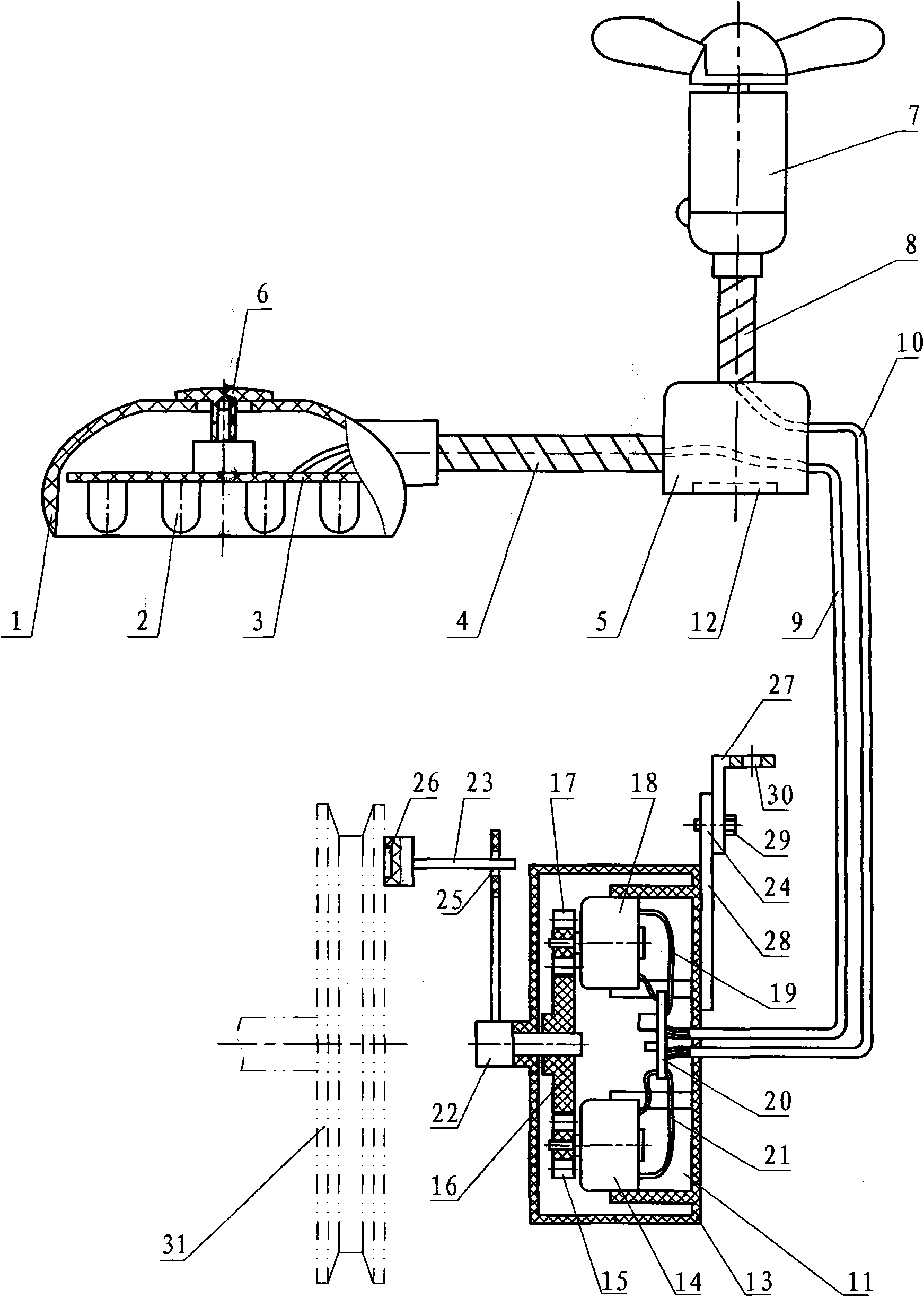
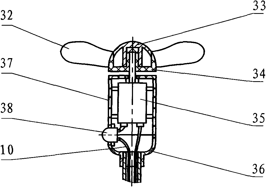
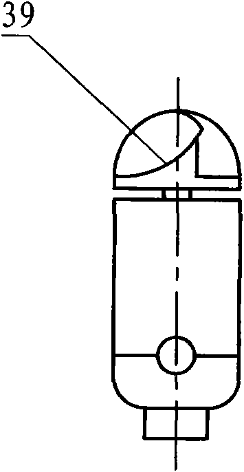
[0021] Combine below Figure 1 to Figure 6 A detailed description will be made to the specific embodiment of the present invention. Embodiment 1: as figure 1 , a self-generating sewing machine fan lamp, including a lamp housing 1, a light-emitting diode group 2, a circuit board 3, a metal hose 4, a lamp holder 5, a fan 7, a metal hose 8, a power cord 9, an electric wire 10, and a lamp housing 1 There is a circuit board 3 inside, the LED group 2 is installed on the circuit board 3, the slide switch 6 is installed on the circuit board 3, the bottom of the lamp holder 5 is provided with a magnet 12, and the lamp holder 5 is provided with a metal hose 4 and a metal Flexible hose 8, one end of electric wire 9 is connected with light-emitting diode group 2, one end of electric wire 10 is connected with micromotor 35 in fan 7, it is characterized in that: the other end of described electric wire 9 and electric wire 10 is provided with power generation device 11. The metal hose 4 c...


PUM


Abstract

A fan lamp of self-generating sewing machine comprises a lamp shell 1, a light-emitting diode group 2, a circuit board 3, a metal hose 4, a lamp pedestal 5, a fan 7, a metal hose 8, an electric wire 9 and an electric wire 10, wherein the circuit board 3 is arranged in the lamp shell 1, the light-emitting diode group 2 is arranged on the circuit board 3, a sliding switch 6 is arranged on the circuit board 3, the bottom of the lamp pedestal 5 is provided with a magnet 12, the metal hose 4 and the metal hose 8 are arranged on the lamp pedestal 5, one end of the electric wire 9 is connected with the light-emitting diode group 2, one end of the electric wire 10 is connected with a micro motor 35 in the fan 7; and the fan lamp is characterized in that the other end of the electric wire 9 and the electric wire 10 is provided with a generating device 11. The invention has the advantages of small volume, easy installation and good safety, achieves illuminating effect without affecting an operator to sew, and improves working efficiency; meanwhile the invention can radiate and lower temperature for the operator and improve workshop working environment.

Description

technical field [0001] The invention relates to a fan lamp which utilizes the mechanical energy of a sewing machine to be converted into electric energy to supply power for lamp illumination and fan blowing for heat dissipation and cooling. Background technique [0002] At present, the sewing machine itself does not have any lighting equipment, and there is a problem of insufficient light at the stitches. Most of the sewing machine lighting used is rectified and stepped down from the mains to provide power to the LED lights. These step-down devices have complex structures and are prone to failure. The use of high-voltage electricity is poor in safety and consumes electricity. In my country, there are quite a lot of sewing equipment used in garment factories and shoe factories. If each sewing machine uses a lighting lamp, the annual power consumption is also quite large. The garment industry needs a large number of sewing machine operators, and the factory lacks effective co...

Claims


Application Information

Patent Timeline
IPC IPC(8): F21S9/04F21V23/00F21V21/096F21V21/32F21V33/00F04D25/08D05B79/00F21W131/4035F21Y101/02F21Y115/10
Inventor 叶信平
Owner 叶信平
Learn More