Laser device with pendulous press roller

一种激光装置、激光束的技术,应用在激光焊接设备、制造工具、焊接设备等方向,能够解决降低焊缝质量等问题,达到简化焊接作业的效果

Active Publication Date: 2009-11-11
LEISTER TECHNOLOGIES
View PDF1 Cites 11 Cited by
  • Summary
  • Abstract
  • Description
  • Claims
  • Application Information

AI Technical Summary

Problems solved by technology

In the case of slight deformations of the three-dimensional workpiece or minor unevennesses on the workpiece, the programmed position of the machining head and thus the pressing cylindrical lens deviates from the ideal position relative to the workpiece, which means that Reduced quality of the resulting weld

Method used


Image

  • Laser device with pendulous press roller
  • Laser device with pendulous press roller
  • Laser device with pendulous press roller

Examples


Embodiment Construction

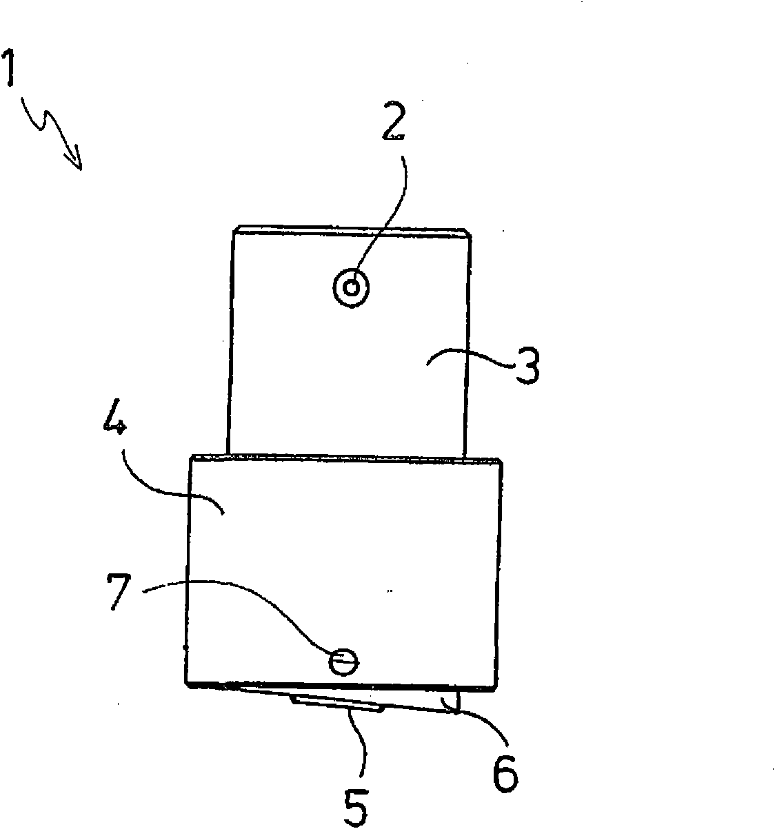
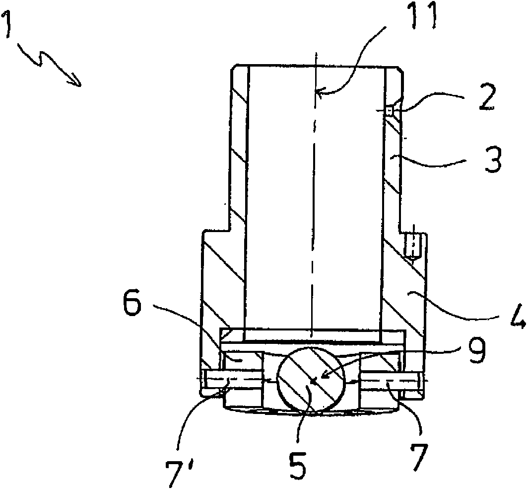
[0020] figure 1 A holding tube 1 of a processing head (not shown in the drawing) of a laser device according to the invention is shown. The holding tube 1 is designed as a stepped hollow cylinder and can be releasably fastened to the processing head by means of a fastening device 2 after it has been inserted with the upper connecting section 3 into the cavity of the processing head. Furthermore, a focusing device is provided in the processing head, which shapes and guides the laser beam incident from the laser source.

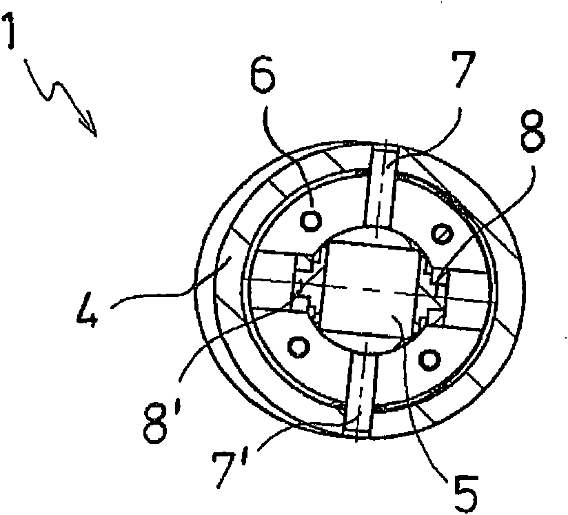
[0021] On the lower fastening section 4 of the holding tube 1 , which is directly connected with an enlarged diameter to the connecting section 3 , a cylindrical lens 5 is movably connected to the holding tube 1 via a receiving ring 6 . The holding barrel 1 and the receiving ring 6 are made of metal. The cylindrical lens 5 is permeable for the laser beam (not shown in the drawing) and consists of glass or a transparent plastic material.

[0022] figure 1 a...


PUM


Abstract

The invention concerns a laser device for joining work pieces made of plastic by means of beam welding technology, with a processing head that has focusing devices for the laser beam. Here, the focusing device that is closest to the work pieces has a rotatably supported cylinder lens in the shape of a roller that focuses the laser beam along a single axis and presses the work pieces together in the form of a line in an area around the impact point of the laser beam. In order to enable the cylinder lens to always contact the surface of the work piece facing the processing head in a precisely tangential manner, the processing head has a pendulum-type suspension for the rotatable cylinder lens. This also makes it possible for the contact pressure exerted by the processing head to always act perpendicularly on the work pieces so that they are pressed together in all welding places in the same way in a defined manner during the welding process.

Description

technical field [0001] The invention relates to a laser device for joining workpieces made of plastic in transmission technology, which laser device has a processing head with a focusing device for the laser beam. In this case, the focusing device closest to the workpiece has a rotatably mounted cylindrical lens designed as a roller, which focuses the laser beam along a single axis and in an The workpiece is pressed linearly in the region of . Background technique [0002] In the transmission technique, the adjoining contact surfaces of the workpieces to be joined are melted under the action of the laser beam and joined together under pressure during subsequent cooling. This method of plastic welding using a laser beam is widely known. In this welding method it is important that the workpieces are clamped together during the welding process, because an important prerequisite for a good welded connection is not only the metering of energy, but also the direct contact betwee...

Claims


Application Information

Patent Timeline
Patent Type & Authority Applications(China)
IPC IPC(8): B29C65/16B23K26/06
CPCB29C65/1635B29C66/80B29C65/16B29C66/8362B29C66/8163B29C66/83411B23K26/023B29C65/1612B29C65/1654B29C66/40B29C66/73921B29C66/8122B29C66/81267B29C66/8167B29C66/8221B29C66/863B29K2995/0027B23K26/037B29K2909/08B29K2901/00
Inventor M·谢特O·欣茨D·沃格勒A·尼德伯格
Owner LEISTER TECHNOLOGIES
Why Eureka
Try Eureka