
Method for controlling traffic signal lights

A technology of a traffic signal light and a control method, applied in the field of traffic signal light control, can solve problems such as intersection pressure and congestion, and achieve the effects of improving traffic capacity, alleviating road congestion, and facilitating promotion.

Inactive Publication Date: 2009-11-04
AOCHENGTONGLI S&T DEV BEIJING
View PDF0 Cites 30 Cited by
  • Summary
  • Abstract
  • Description
  • Claims
  • Application Information

AI Technical Summary

Problems solved by technology

[0004] However, this control method controls the congested vehicles on the entry road section. Although the congestion at the intersection is all alleviated, the vehicles that are blocked on the entry road do not drive through the intersection, which still causes pressure on the traffic at the intersection. Under the current urban road conditions, there is often a phenomenon of overall congestion of the entire road from one intersection to another during peak hours. This method of limiting vehicles to the road cannot solve this problem well.

Method used


Image

  • Method for controlling traffic signal lights

Examples


Embodiment Construction

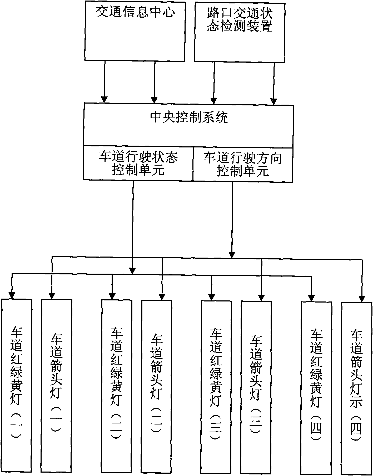
[0009] see figure 1 , the present invention provides a kind of traffic signal light control method, and it is provided with the traffic signal light that is used for controlling the vehicle that enters the road at the crossing, and is provided with central control system to control the display state of each traffic signal light, and described traffic signal light and driveway One-to-one correspondence, displaying the state and driving direction of vehicles in the lane, and the central control system determines the driving conditions and driving directions of each lane according to the actual road conditions.

[0010] Described traffic signal light comprises traffic light and blue arrow light, and wherein traffic light is used for displaying the driving state of real-time lane (allowing to enter, must not enter and transition), and blue arrow light is used for displaying the real-time lane. direction of travel.

[0011] The traffic, green and yellow lights adopt arrow lights t...


PUM


Abstract

The invention relates to a method for controlling traffic signal lights, wherein an intersection is provided with the traffic signal lights for controlling the travel of vehicles entering roads, and a central control system for controlling the display state of each traffic signal light; the traffic signal lights correspond to the roads in a one to one mode and display the conditions and travel directions of vehicles in the road; and the central control system determines the travel condition and the travel direction of each driveway according to the actual condition of the road. By adopting the method, the travel direction and the green light time of each driveway at an entering intersection can be controlled automatically, and the traffic capacity of the intersection is effectively used by controlling both the traffic direction and the traffic flow so as to reduce road congestions.

Description

technical field [0001] The invention relates to a traffic signal lamp control method, which can flexibly arrange the driving flow of each direction and each lane, effectively utilize the traffic capacity of road crossings, and reduce road congestion. Background technique [0002] The existing traffic signal controllers all have the function of induction control. According to the traffic flow signal at the corresponding entrance detected by the vehicle detector (ground sense coil, video detector), the green light time of the current phase is adjusted in real time, so as to achieve the signal timing matching with the vehicle. The purpose of traffic flow matching, for example, if the vehicle detector detects that the traffic flow at the entrance of a certain intersection is larger than the traffic flow at other entrances, then the green light lighting time corresponding to the entrance will be extended. But along with the increase of urban motor vehicles, it is more common that...

Claims


Application Information

Patent Timeline
Patent Type & Authority Applications(China)
IPC IPC(8): G08G1/07G08G1/08G08G1/09G08G1/095G08G1/04G08G1/042
Inventor 梁治龙
Owner AOCHENGTONGLI S&T DEV BEIJING
Learn More