
Battery pack

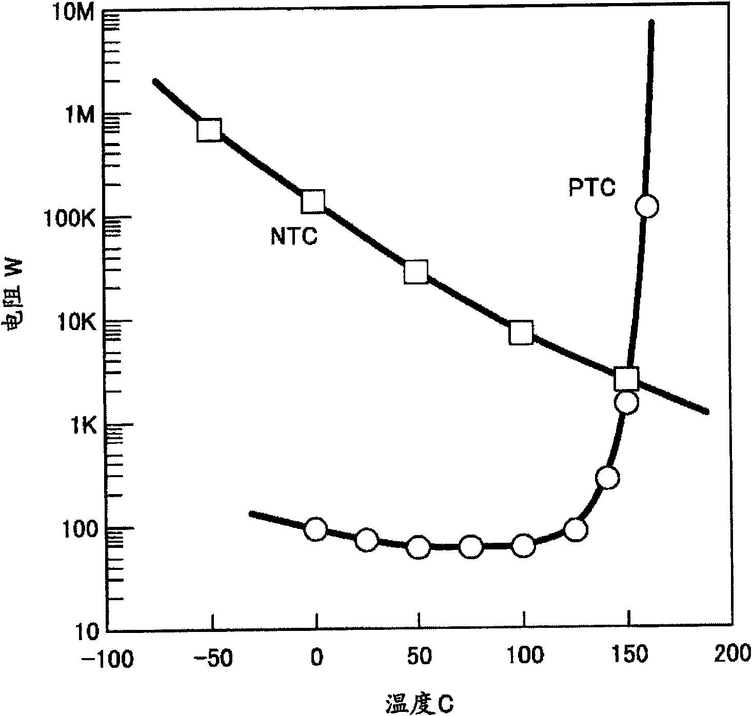
By connecting a series circuit of the thermistor and resistor in parallel in the battery pack and a temperature abnormality detection unit, high-precision temperature detection and control is achieved, which solves the problem in the existing technology of being unable to accurately detect the temperature of the battery pack and prevent itself from heating. , ensuring the safety and reliability of the battery pack.

Active Publication Date: 2009-10-28
MITSUMI ELECTRIC CO LTD
View PDF6 Cites 8 Cited by
  • Summary
  • Abstract
  • Description
  • Claims
  • Application Information

AI Technical Summary

Problems solved by technology

[0010] Image 6 The conventional example shown does not have a protection function corresponding to the temperature of the battery pack
in addition, Figure 7 Although the conventional example shown has a protection function corresponding to the temperature of the battery pack, since a predetermined voltage is applied from the charging device via a voltage dividing resistor, there is a problem that the predetermined voltage of the charging device changes or the charging device is present. In the case of piezoresistance error, the temperature of the battery pack cannot be accurately detected

Method used


Image

  • Battery pack
  • Battery pack
  • Battery pack

Examples


Embodiment approach

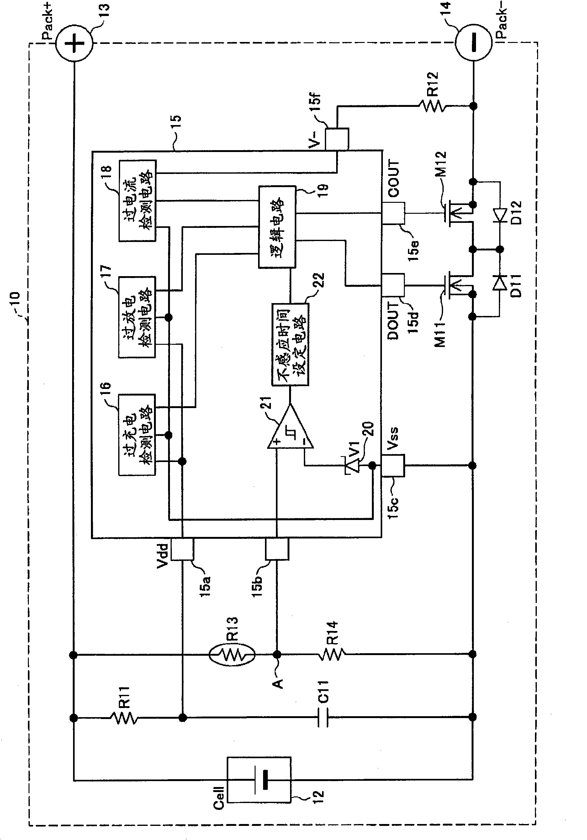
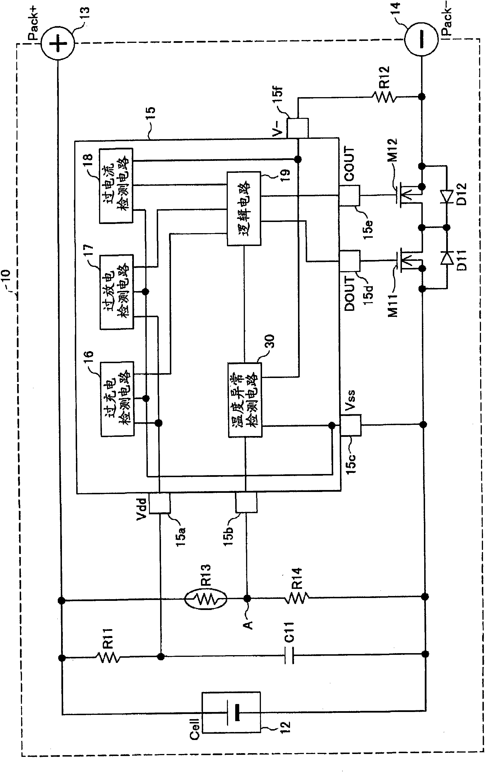
[0045] image 3 A block diagram showing an embodiment of the battery pack of the present invention. In this figure, for and figure 1 The same symbols are assigned to the same parts.

[0046] exist image 3 In this case, a series circuit of a resistor R11 and a capacitor C11 is connected in parallel with the lithium ion battery 12 . The positive electrode of the lithium ion battery 12 is connected to the external terminal 13 of the assembled battery 10 , and the negative electrode is connected to the external terminal 14 of the assembled battery 10 via n-channel MOS transistors M11 and M12 for current interruption.

[0047] The drains of the MOS transistors M11 and M12 are connected together, the source of the MOS transistor M11 is connected to the negative electrode of the lithium ion battery 12 , and the source of the MOS transistor M12 is connected to the external terminal 14 . In addition, body diodes D11 and D12 are equivalently connected between the drain and the sou...


PUM


Abstract

A battery pack including a protection circuit configured to detect over-charge, over-discharge and over-current of a rechargeable battery to turn off a switch element, the switch element provided at a wire provided between the rechargeable battery and a load circuit or a charging device; a series circuit of a thermistor and a resistor, the series circuit provided in parallel to the rechargeable battery, the thermistor thermally connected to the rechargeable battery; and an abnormal temperature detection unit provided in the protection circuit, wherein the abnormal temperature detection unit operates the switch to be in an off state when the temperature of the rechargeable battery is higher than a predetermined temperature, and when a voltage of the wire is higher than a threshold voltage of a forward drop voltage of a body diode in the switch, the abnormal temperature detection unit operates the switch to be in an on state.

Description

technical field [0001] The present invention relates to a battery pack, and more particularly to a battery pack capable of detecting overcharge, overdischarge, and overcurrent of a secondary battery, and turning off a switching element provided on a wiring between the secondary battery and a load or a charging device ( OFF) protection circuit for the battery pack. Background technique [0002] In recent years, lithium ion batteries have been installed in portable devices such as digital cameras as secondary batteries. Lithium-ion batteries have low ability to cope with overcharge and overdischarge, so they are used in the form of battery packs equipped with overcharge and overdischarge protection circuits. [0003] Figure 6 and Figure 7 A block diagram showing various examples of conventional battery packs. exist Figure 6 In , a series circuit of a resistor R1 and a capacitor C1 is connected in parallel with the lithium ion battery 2 . The positive electrode of the li...

Claims


Application Information

Patent Timeline
Patent Type & Authority Applications(China)
IPC IPC(8): H02H7/18H02H5/04H01M10/48H01M10/60H01M10/613H01M10/637H01M50/574H02J7/00
CPCY02E60/12H02J2007/0037H01M2/348H01M10/052H02J2007/0039H01M2/34H02J7/0031H02J2007/004H02J7/00302H02J7/00304H02J7/00306Y02E60/10H01M50/581H01M50/574H01M10/63H02J7/00
Inventor 武田贵志竹下顺司
Owner MITSUMI ELECTRIC CO LTD
Learn More