Circuit board connector

A technology for connectors and circuit boards, applied in the direction of connection, circuit, fixed connection, etc., can solve the problems of undesired generation of stress, cracks, etc., and achieve the effect of enhancing connection reliability.

Inactive Publication Date: 2009-10-28
YAZAKI CORP
View PDF2 Cites 10 Cited by
  • Summary
  • Abstract
  • Description
  • Claims
  • Application Information

AI Technical Summary

Problems solved by technology

[0006] With this type of circuit board connector, there is a problem that, since the terminals 110A and 110B are press-fitted into and fixed in the connector housing 101, tension is generated between the circuit board and the connector housing due to heat cycle or the like. In the case of poor thermal shrinkage, stress is undesirably generated in the terminals 110A and 110B, possibly causing cracks in the portion of the board fixing portion 117 soldered to the circuit board

Method used


Image

  • Circuit board connector
  • Circuit board connector
  • Circuit board connector

Examples


Embodiment Construction

[0025] Embodiments of the present invention will now be described with reference to the accompanying drawings.

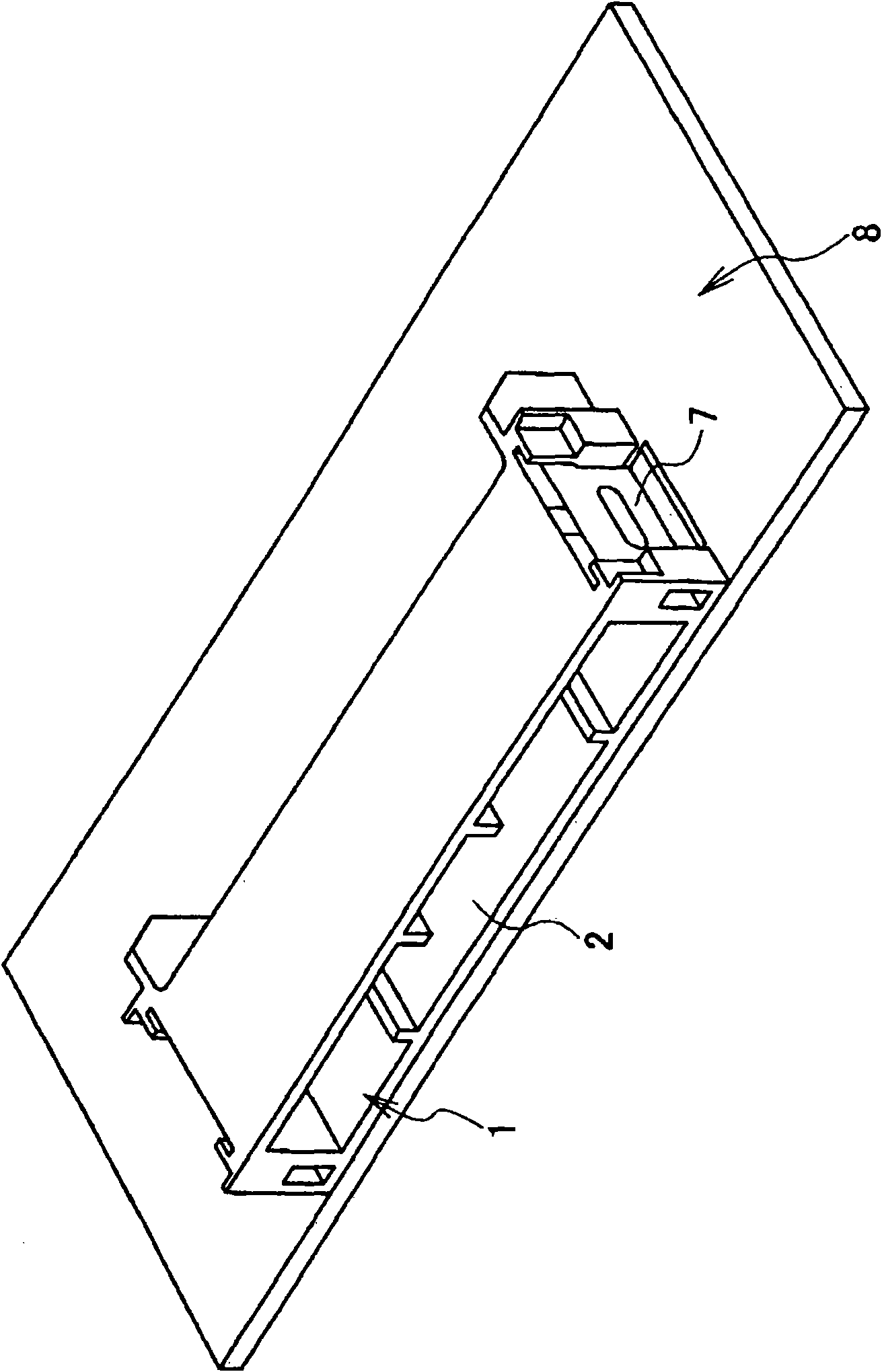
[0026] figure 1 is a perspective view showing the structure of a terminal used in the circuit board connector according to the embodiment. figure 2 is an external perspective view viewed from the front side of the circuit board connector according to the embodiment. image 3 is an external perspective view from the rear side of the board connector. Figure 4 is the rear view of the essential part of the board connector. Figure 5 is its enlarged view. Image 6 is a horizontal cross-sectional view of the board connector. Figure 7 is its enlarged view.

[0027] Such as Figure 1 to Figure 7 As shown in , the circuit board connector according to this embodiment includes: a resin-made connector housing 1 mounted on a circuit board 8 so that the front and rear directions of the circuit board connector are oriented along the direction of the circuit board 8, And...


PUM


Abstract

A circuit board connector is provided. The circuit board connector includes: a connector housing which is mounted on a circuit board; and a terminal which is press-fitted into the terminal press-fitting hole of the connector housing. The terminal includes: a terminal connecting portion which is disposed through the rear side of the connector housing to be connected to a mating connector; a press-fitting portion to be fixed to the connector housing; a board fixing portion fixed to the circuit board by soldering; and a coupling portion extending and bent toward a side of the circuit board to couple the press-fitting portion with the board fixing portion. The circuit board connector also includes a stress absorbing portion provided with a center hole which is provided on a midway of the coupling portion so as to absorb a stress by being deformed.

Description

technical field [0001] The invention relates to a circuit board connector mounted on a circuit board. Background technique [0002] Examples of this type of circuit board connector are shown in JP-A-2006-100231 and JP-A-2005-116230, for example. Figure 8 is a schematic diagram of a circuit board connector described in JP-A-2006-100231. Figure 9A with Figure 9B is a schematic diagram of the terminals of the connector. [0003] Such as Figure 8 As shown in , the circuit board connector includes: a connector housing 101 made of resin, and a plurality of metal terminals 110A and 110B. port 102; the plurality of metal terminals 110A and 110B are press-fitted into press-fit holes 104 in the rear wall 103 of the connector housing 101 from the rear side, and are fixed therein. [0004] In both terminals 110A and 110B, the Figure 9A The terminal 110A shown in is press-fitted into the terminal press-fit hole 104 in the upper step of the connector housing 101, while Figure 9...

Claims


Application Information

Patent Timeline
Patent Type & Authority Applications(China)
IPC IPC(8): H01R12/20H01R13/02H01R13/428
CPCH01R23/7063H01R23/7073H01R12/57H01R12/707H01R12/714H01R13/40H01R12/716H01R12/724
Inventor 坂元信幸
Owner YAZAKI CORP
Why Eureka
Try Eureka