
Non-imaging optical directional light distribution method for LED light source

A non-imaging optics and LED light source technology, applied in the field of non-imaging optical light distribution, can solve the problems of inability to fundamentally improve the Lambertian property of LED light sources, inability to achieve directional light distribution, poor light distribution uniformity, etc. Light distribution control, beneficial to human eye health, and the effect of large light angle

Inactive Publication Date: 2009-10-28
XIAN ZHIHAI POWER TECH
View PDF0 Cites 10 Cited by
  • Summary
  • Abstract
  • Description
  • Claims
  • Application Information

AI Technical Summary

Problems solved by technology

[0010] The purpose of the present invention is to provide a non-imaging optical directional light distribution method for LED light sources, which solves the problem that the prior art cannot fundamentally improve the Lambertian characteristics of LED light sources, so that directional light distribution cannot be realized, resulting in poor light distribution uniformity , technical problems of low light efficiency

Method used

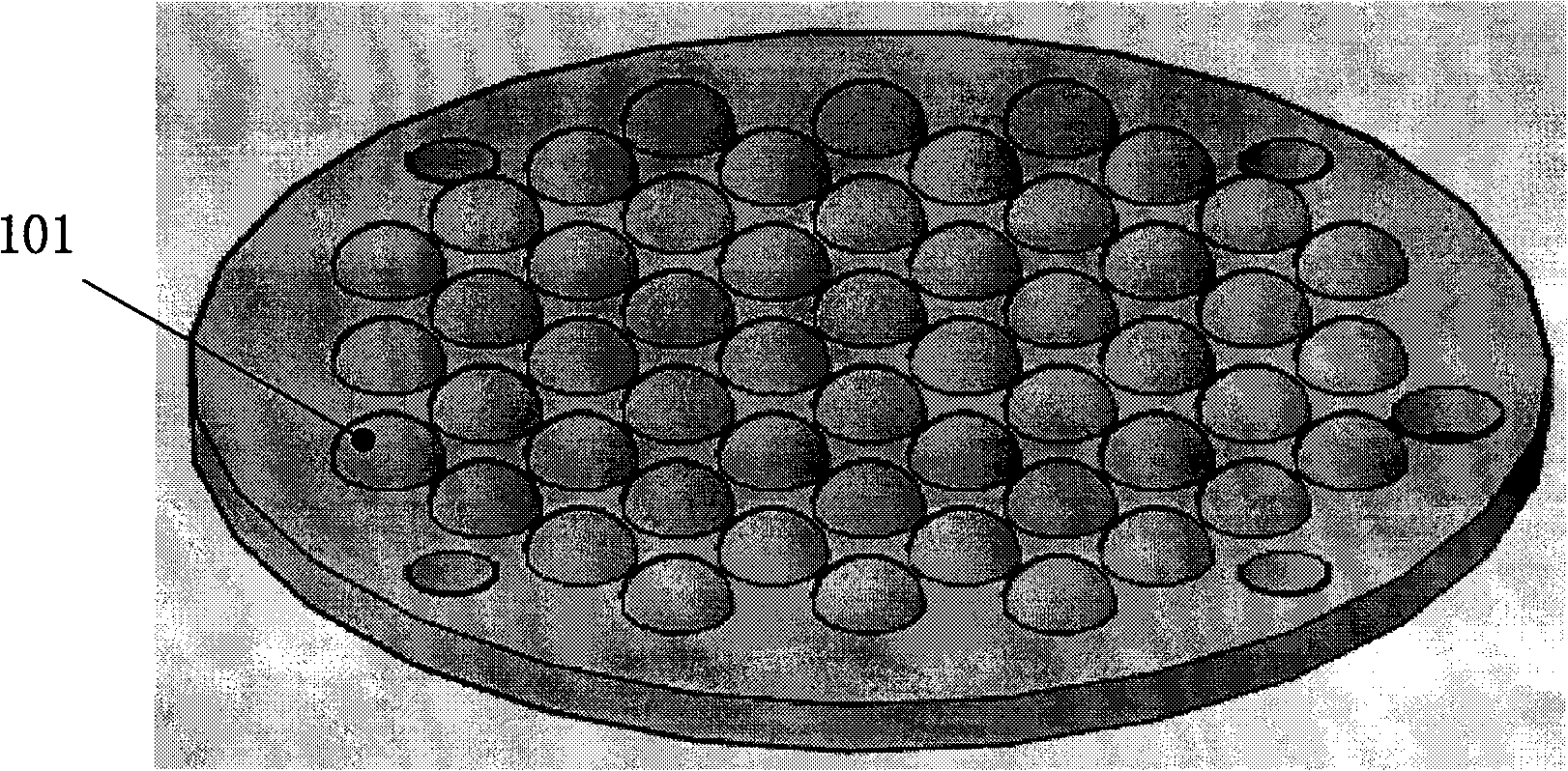
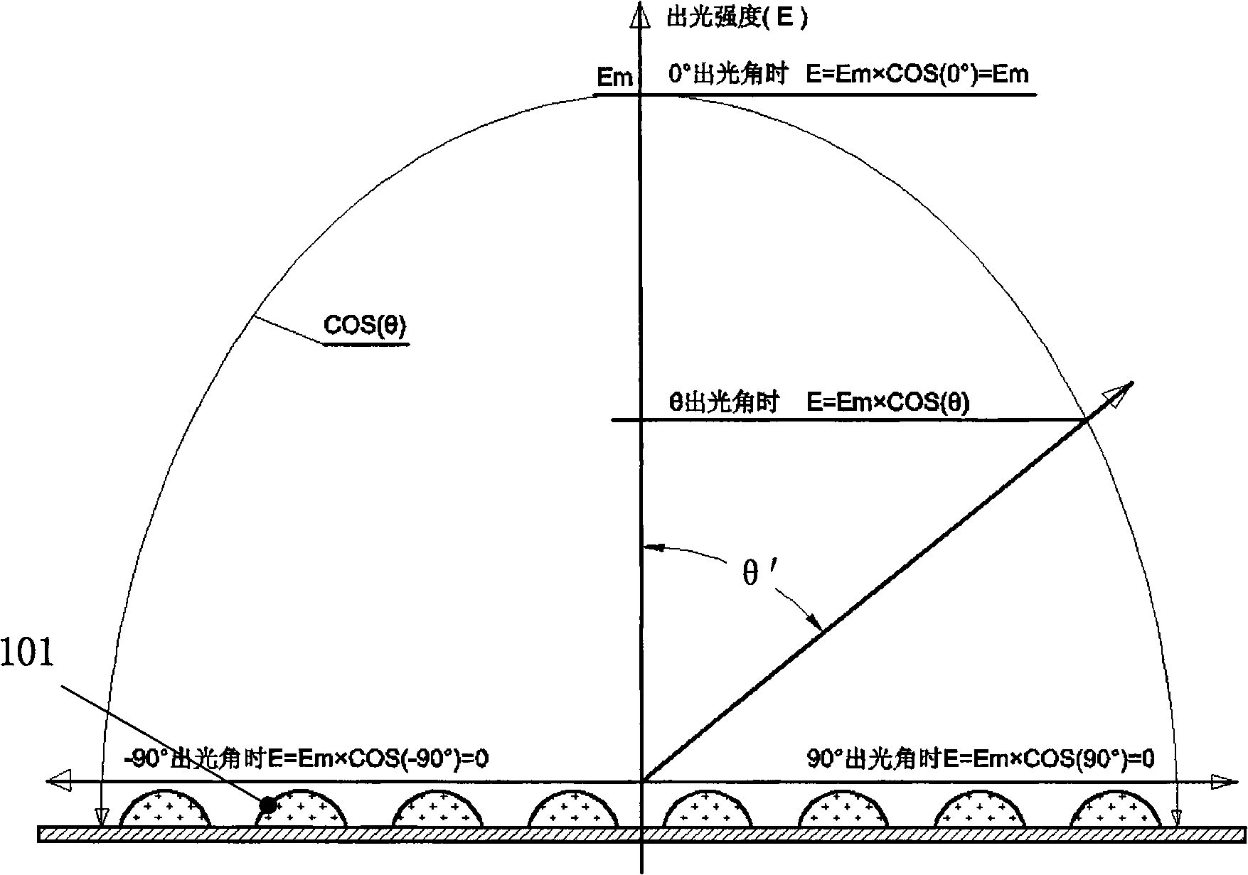
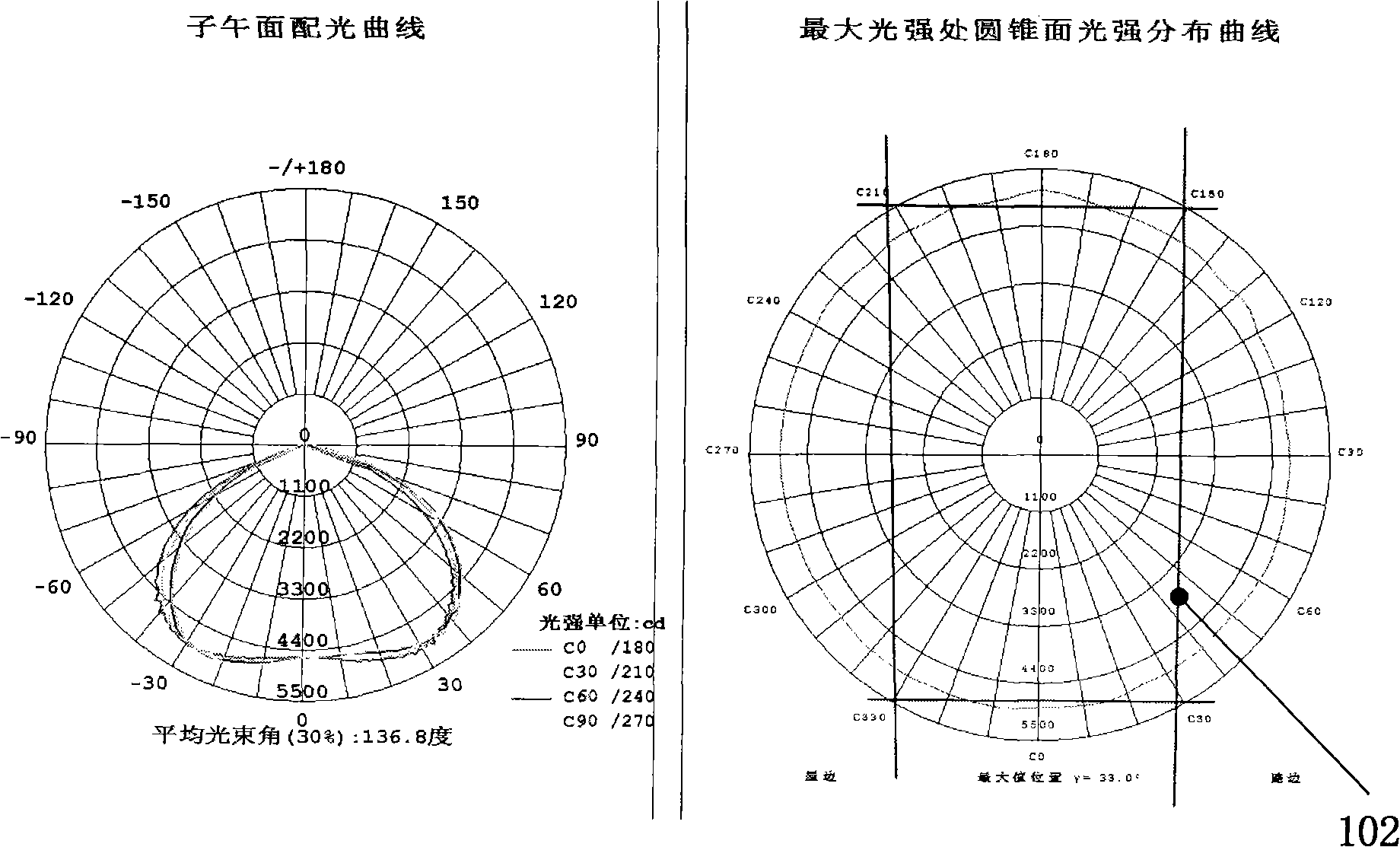

Image

  • Non-imaging optical directional light distribution method for LED light source
  • Non-imaging optical directional light distribution method for LED light source
  • Non-imaging optical directional light distribution method for LED light source

Examples


Embodiment Construction

[0044] The principle of directional refraction of the light distribution lens of the present invention:

[0045] (1.1) Snell's law: When light is incident on the interface of different media, reflection and refraction occur. The incident light and refracted light are on the same plane, and the angle with the interface normal satisfies the following relationship:

[0046] Snell formula N m sinθ m =N n sinθ n ,

[0047] Where N m And N n Are the refractive indices of the two media, θ m And θ n They are the angle of incidence and the angle of refraction.

[0048] (1.2) Principle of directional refraction of light distribution lens:

[0049] Such as Figure 5 As shown, the refractive index of the incident medium of the light distribution lens N 1 、Refractive index of light distribution lens N 2 , The refractive index of the exit medium after the LED light passes through the light distribution lens N 3 ;The incident angle θ of the LED light incident on the light distribution lens 1 , Th...


PUM


Abstract

The invention relates to a non-imaging optical directional light distribution method for an LED light source, which comprises the following steps: determining an emergence angle theta4 of LED light passing through a light distribution lens according to the requirement of a light spot, and selecting a refractive index N1 of an incident medium of the LED light, a refractive index N2 of the light distribution lens and a refractive index N3 of an emergent medium to acquire an incidence angle theta1= f(N1, N2, N3 and theta4). By using the incidence angle theta1 as an included angle theta of an incident face and an emergent face of the light distribution lens, the incident face and the emergent face of the light distribution lens can be acquired. The LED light is incident onto the light distribution lens by the incidence angle theta1 and then is refracted by the light distribution lens to form LED directional light. The method solves the technical problems that the prior art cannot radically improve the Lambert property of the LED light source so that directional light distribution cannot be realized, the light distribution evenness is poor and the light efficiency is low, can directionally control the distribution of light intensity of the LED light source so as to realize precise light distribution control, and has the advantages of high reliability, energy conservation and environmental protection.

Description

Technical field [0001] The invention belongs to the technical field of non-imaging optical light distribution, and specifically relates to a non-imaging optical directional light distribution method of an LED light source. Background technique [0002] Functional lighting fixtures such as street lights and tunnel lights require that the illuminance at each point in the lighting range must meet the minimum illuminance index, the highest glare requirement index, the light intensity uniformity index, and the illumination area limit requirements required by the lighting specification, which affects the reliability of the product And energy saving, environmental protection performance and other requirements are also very high. In order to improve the lighting effect and protect the health of human eyes, it is necessary to use lamps to carry out the lighting distribution of the optical system, that is, in a given road position and a given road area, a light field with uniform illuminan...

Claims


Application Information

Patent Timeline
IPC IPC(8): F21V5/04H01L33/00F21Y101/02
CPCF21V5/00G02B5/0215G02B3/0006G02B3/08H01L33/58F21Y2101/02G02B5/0278F21Y2115/10
Inventor 胡家培胡民海
Owner XIAN ZHIHAI POWER TECH
Learn More