Sliding track mechanism

A technology of slide rails and pulleys, applied in the field of slide rail mechanisms, which can solve problems such as the inability to adjust the upper and lower positions

Inactive Publication Date: 2009-10-28
王中好
View PDF0 Cites 2 Cited by
  • Summary
  • Abstract
  • Description
  • Claims
  • Application Information

AI Technical Summary

Problems solved by technology

After the pulley is fixed on the pulley bracket, its up and down position cannot be adjusted

Method used


Image

  • Sliding track mechanism
  • Sliding track mechanism

Examples


Embodiment Construction

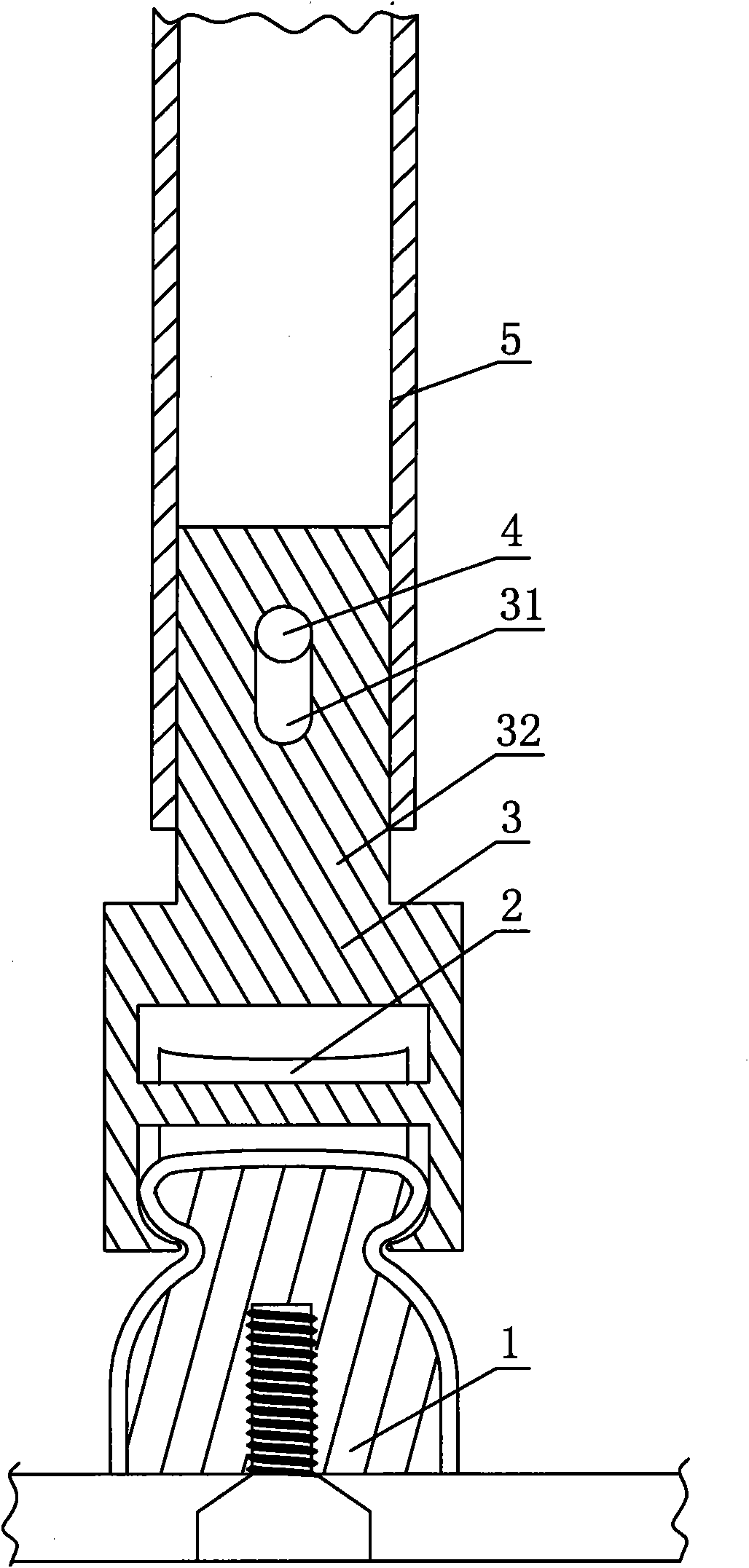
[0011] Such as figure 1 As shown, it is a preferred embodiment of a slide mechanism of the present invention, including a fixed track 1 and a pulley 2 sliding on the track, the pulley is arranged on a pulley member 3, and the pulley member is installed on a pulley bracket 5, wherein the The pulley bracket 5 is a hollow tube, and the mounting arm 32 at the pulley part rear portion is arranged in the hollow tube. The mounting arm has a through groove 31, and the pulley positioning core 4 runs through the hollow tube and the through groove to fix the pulley part on the hollow tube. The longitudinal length of the through-slot is greater than the outer diameter of the positioning core, and the pulley is adjusted up and down along the positioning core through the through-slot. The pulley bracket is a flat hollow tube, and the pulley pieces are sheet-shaped to cooperate with the pulley bracket.

[0012] Such as figure 2 As shown, it is another embodiment of a slide rail mechanism ...


PUM


Abstract

The invention discloses a sliding track mechanism which comprises a fixed track and pulleys sliding on the track, and the pulleys are arranged on a pulley part which is arranged on a pulley bracket, wherein the pulley bracket is a hollow pipe, an installation arm at the back of the pulley part is arranged in the hollow pipe and provided with a through groove, a pulley positioning core passes through the hollow pipe and the through groove and fixes the pulley part on the hollow pipe, the longitudinal length of the through groove is larger than the outer diameter of the positioning core, and the position of the pulley part is adjusted up and down by the through groove along the positioning core. As the technical proposal is adopted, the position of the pulley part can be adjusted up and down by the through groove along the positioning core, thereby being suitable for a plurality of needs in reality.

Description

technical field [0001] The invention relates to a slide rail mechanism, in particular to a slide rail mechanism used in a mobile garage. Background technique [0002] In the mobile garages currently on the market, the track adopts directional determination, and the pulley slides on the track. Wherein the pulley is located on the pulley piece, and the pulley piece is installed on the pulley bracket. After the pulley member is fixed on the pulley bracket, its up and down position cannot be adjusted. In the process of use, there is often a need to adjust its up and down position. Contents of the invention [0003] The technical problem to be solved by the present invention is to provide a slide rail mechanism capable of adjusting the upper and lower positions of the pulley. [0004] In order to solve the above-mentioned technical problems, the present invention adopts the following technical solutions: a slide rail mechanism, comprising a fixed track and a pulley sliding o...

Claims


Application Information

Patent Timeline
IPC IPC(8): E04H6/04
Inventor 王中好
Owner 王中好
Why Eureka
Try Eureka