
Error correction system for a class-d power stage

A technology of switching power and power amplification, applied in amplifier types, amplifiers with semiconductor devices/discharge tubes, electrical components, etc., to achieve perfect reproduction and improved amplification effects

Inactive Publication Date: 2009-10-21
BANG & OLUFSEN ICEPOWER
View PDF10 Cites 12 Cited by
  • Summary
  • Abstract
  • Description
  • Claims
  • Application Information

AI Technical Summary

Problems solved by technology

[0011] Different prior art systems and methods address some of the above problems, but not all at the same time, and there is a need to achieve higher performance levels

Method used


Image

  • Error correction system for a class-d power stage
  • Error correction system for a class-d power stage
  • Error correction system for a class-d power stage

Examples


Embodiment Construction

[0052] Referring to FIG. 1 , there is shown a block diagram illustrating the principle of a prior art power amplifier with a control loop;

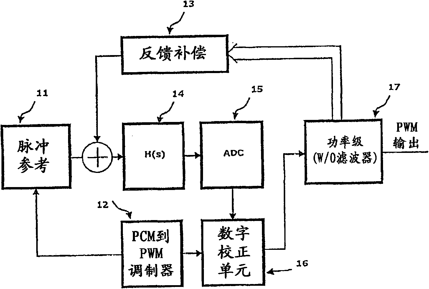
[0053] Referring to FIG. 2, a prior art power conversion method based on digital pulse modulation is schematically shown;

[0054] Referring to Figure 3, another example of a prior art circuit is shown.

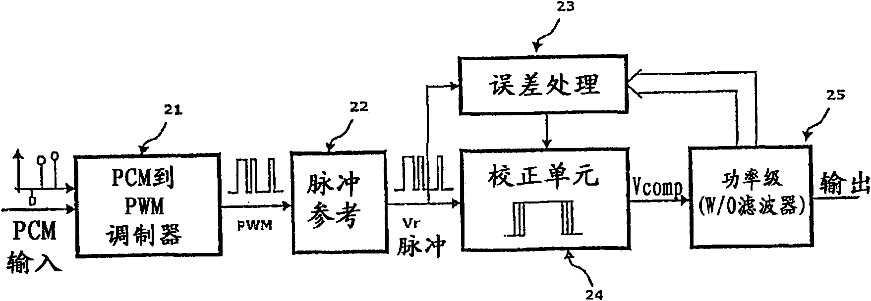
[0055] refer to Figure 4 , shows an embodiment of the system according to the invention, where a general system using feedback before or after the demodulation filter is shown. First, the PCM is converted into a pulse-coded signal 41 . Pulse coded signals can be of many types, but are referred to here as PWM for convenience. The next step consists in generating a reference signal 42, wherein the generated PWM signal has a stable amplitude. This is often referred to as a 1-bit D / A converter. Since the generation of the error signal is now a summing function 43 rather than a differential function, an advantageous approach is to inver...


PUM


Abstract

The present invention relates to a method for correcting for a source of non-linearity and noise introduced in a switching power amplification stage during power amplification of a pulse-modulated reference signal from a pulse modulator, where the method comprises the following steps: - providing an output stage embedded in an analogue self-oscillating control loop able to receive a pulse-referenced input signal; - generating a feedback signal from the switching power amplification stage or after a demodulation filter; - deriving an error signal by comparing the feedback signal with the reference signal; - filtering the error signal by a low pass filter for reducing the higher harmonics of the carrier; - adding a compensator for generating high loop gain in the audio band; - feeding the compensator output to a zero cross detector or comparator, thus providing a carrier for re-modulation or re-timing by feeding the filtered signal to a zero cross detector or comparator, which controls the output stage. The invention furthermore relates to various systems for implementing the above method.

Description

technical field [0001] The present invention relates generally to error correction systems and power conversion systems implementing such error correction systems. More particularly, the present invention relates to a pulse-referenced control system for reducing errors introduced by a Class D output stage. Applications are direct digital audio power conversion and general purpose DC-DC or DC-AC power conversion systems controlled from the digital domain. Background technique [0002] The advantages of power amplification based on switching power stages are well known. High efficiency offers several advantages in terms of minimal weight and volume, higher power handling capabilities and increased reliability. The basic elements in switching power amplification are modulator, switching power stage and demodulation filter for reconstructing the modulated signal. The nonlinearity of the switching power stage presents a significant obstacle in maintaining modulator performance...

Claims


Application Information

Patent Timeline
Patent Type & Authority Applications(China)
IPC IPC(8): H03F3/217H03F1/32
CPCH03F2200/144H03F1/32H03M1/1033H03F2200/372H03F3/217H03M1/822H03F2200/03H03F2200/351G06F21/1073G06F17/00
Inventor O·N·尼尔森
Owner BANG & OLUFSEN ICEPOWER
Learn More