
Residual current circuit breaker

A leakage circuit breaker and circuit technology, which is applied in the direction of circuit devices, emergency protection circuit devices, electrical components, etc., can solve the problems of enlarged test circuit installation space, increased test circuit installation space, and increased manufacturing costs, achieving accurate and Effects of stable leakage test, accurate and stable operation test, and reduced installation space

Inactive Publication Date: 2009-10-21
FUJI ELECTRIC FA COMPONENTS & SYST CO LTD
View PDF1 Cites 8 Cited by
  • Summary
  • Abstract
  • Description
  • Claims
  • Application Information

AI Technical Summary

Problems solved by technology

[0010] However, in such a conventional device, since it is necessary to set the number of current-limiting resistance elements and selection switches corresponding to the type of rated voltage used, the installation space of the test circuit increases and the number of parts decreases. increase, there is a problem that the manufacturing cost increases
[0011] Moreover, especially when the rated voltage is high, a large voltage is often applied between the contacts when the test switch is turned on, so it is necessary to increase the contact interval of the test switch to improve the withstand voltage, so there is still the problem of increasing the size of the switch.
[0012] In an earth leakage circuit breaker having such a latter test circuit, when the rated voltage used is high, the voltage applied to the current-limiting resistance element during the test operation is high and the power consumption is large
For this reason, in the prior art, a current-limiting resistance element with a large power wattage is used, and the current-limiting resistance element is divided into several in series, thereby sharing power consumption
[0013] Therefore, in such conventional devices, since it is necessary to use a current-limiting resistance element with a large wattage or divide the current-limiting resistance element into a plurality in series to share the power consumption, the installation space of the test circuit becomes large and the number of parts increases, thereby There is a problem of rising manufacturing costs

Method used


Image

  • Residual current circuit breaker
  • Residual current circuit breaker
  • Residual current circuit breaker

Examples


Embodiment 1

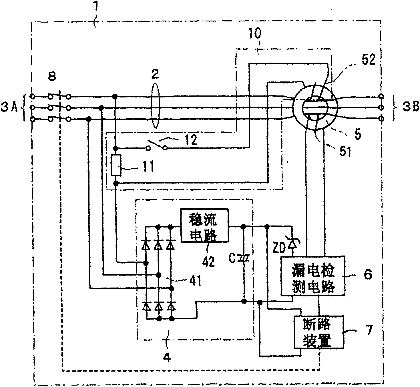
[0032] figure 1 It is a structural diagram showing Example 1 of the present invention.

[0033] in figure 1 Among them, 1 is a leakage circuit breaker, and usually all the structural elements are housed in a molded case made of insulating resin and formed compactly. The earth leakage circuit breaker 1 is equipped with: the main circuit 2 connecting the power supply side connection terminal 3A and the load side connection terminal 3B; the opening and closing section 8 that makes the main circuit 2 on and off; The zero-phase converter 5 of the leakage current flowing through the main circuit; the leakage detection circuit 6 that monitors the detection current of the leakage detection coil 51 of the zero-phase converter 5 and judges whether there is a leakage; according to the leakage detection circuit 6 An output signal indicating a leakage, a circuit breaker 7 that interrupts the on-off mechanism of the opening and closing section 8 to open the opening and closing section; and a...

Embodiment 2

[0045] Secondly, Figure 4 The structure of Embodiment 2 of the present invention is shown in.

[0046] This embodiment 2 is different from embodiment 1 only in the input resistance R 1 , R 2 And R 3 In each phase connected to the AC input side of the rectifier circuit 41 of the power supply circuit 4, the other structures are the same.

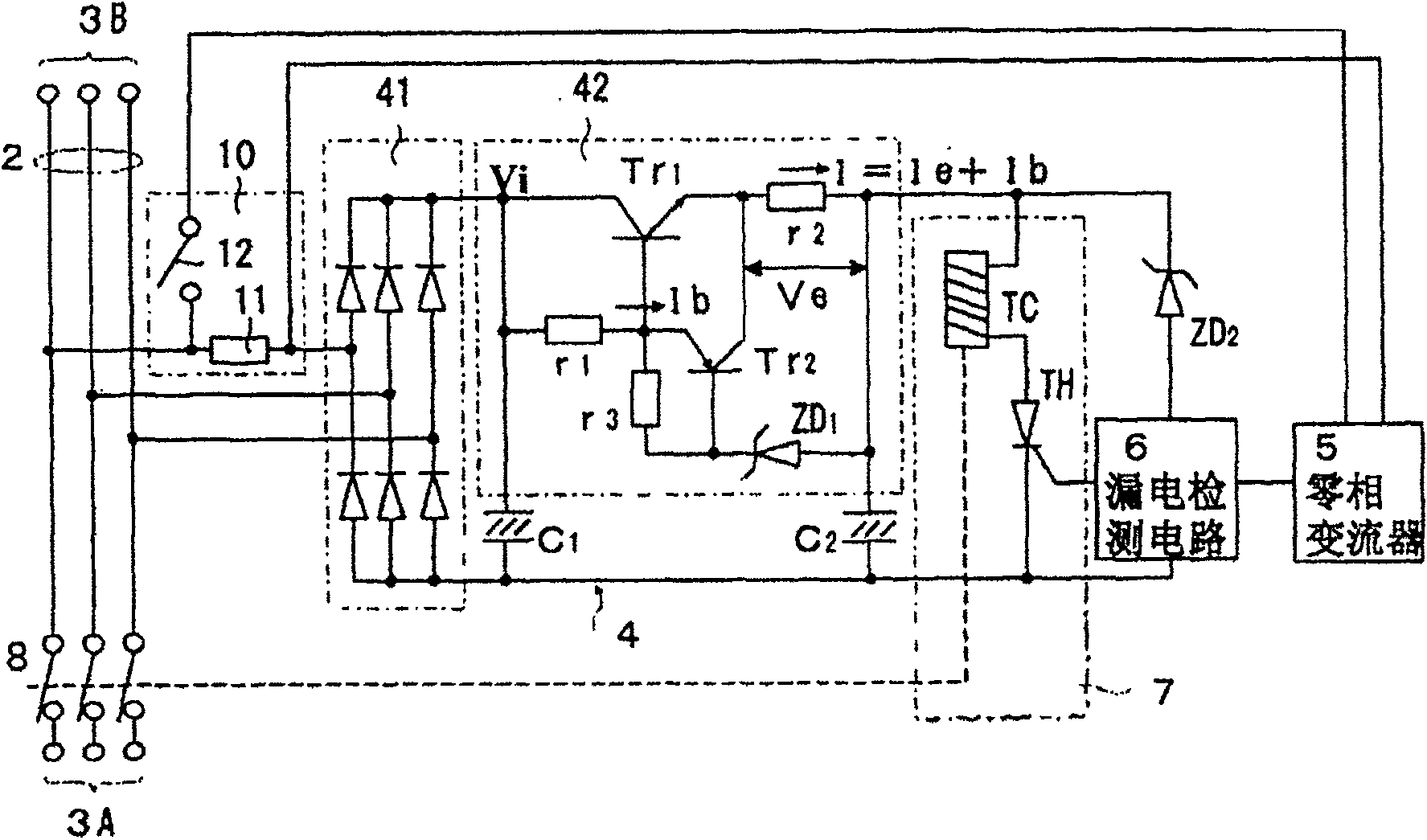
[0047] In this way, if the input resistance R 1 , R 2 , R 3 Connected to the power supply circuit 4, these resistance elements and the smoothing capacitor C in the power supply circuit 4 can be used 1 (Reference figure 2 ) Form a filter circuit, so it can absorb high frequency surge voltage, and therefore can improve the surge voltage withstand voltage of the power supply circuit 4 and the test switch 12 of the test circuit 10.

Embodiment 3

[0049] Figure 5 It is a block diagram showing Embodiment 3 of the present invention.

[0050] The Figure 5 Example 3 shown is to combine two Zener diodes ZD 3 And ZD 4 It is an embodiment in which the reverse series connection is connected to both ends of the test resistance element 11, and the terminal voltage of the test resistance element 11 is limited below a certain voltage determined by the Zener diode. Even without reducing the resistance value of the test resistance element 11, by installing a Zener diode, the voltage at both ends can be limited below a certain value, and the burden of the AC voltage of the test switch 12 can be reduced, so the contacts can be spaced apart Narrower, the overall size of the switch can be miniaturized.


PUM


Abstract

The present invention discloses a residual current circuit breaker of a test circuit, which has the advantages of simple structure, small size and accurate electric leakage test. The residual current circuit breaker comprises the following components: an open and close part which switches on and off a main circuit; a zero-phase current transformer which is traversed by all phase conductor of the main circuit; an electric leakage detecting circuit which determines the generation of the current leakage according to the output current of the electric leakage detecting coil of the zero-phase current transformer; an operating time setting circuit for setting the operating time of the electric leakage detecting circuit; a breaking device for breaking and switching off the open and close part according to the output signal of the electric leakage detecting circuit, which represents the generation of electric leakage; a power source circuit which supplies the electric power to the electric leakage detecting circuit; and a test circuit which is provided with a test switch which supplies the test current to the test coil of the zero-phase current transformer, wherein the test circuit is installed with a unit which operates together with the test switch and is set to a preset operating time irrespectively with the setting of the operating time setting circuit.

Description

[0001] This application is a divisional application of the application of the same name with the application number 200410090718.0 filed on November 8, 2004 Technical field [0002] The present invention relates to a leakage circuit breaker used to detect leakage in a power distribution system connected to a motor and various other loads so as to prevent the spread of accidents in the future, and particularly relates to the improvement of the test circuit. Background technique [0003] In order to correctly perform the operation test of the leakage circuit breaker, various efforts have been made so far in the leakage test circuit of the leakage circuit breaker. One example is shown in Patent Document 1. Figure 7 The structure of the earth leakage circuit breaker shown in Patent Document 1 is shown in. [0004] Figure 7 The leakage circuit breaker in has multiple rated voltages, for example, there are three rated voltages of 100, 200 and 400V. The earth leakage circuit breaker 1...

Claims


Application Information

Patent Timeline
Patent Type & Authority Applications(China)
IPC IPC(8): H02H3/347H01H83/14H01H83/04H01H83/02H02H1/06H02H3/33
CPCH02H3/335H02H1/06H01H83/04
Inventor 辻伸彦浅野久伸
Owner FUJI ELECTRIC FA COMPONENTS & SYST CO LTD
Learn More