


Quick Research
Generate reliable direction feasibility study reports for your R&D in just a few steps.

Technical Q&A
Discover and master advanced knowledge NOW. Basics, ideas, possibilities, all at once.

Find Solutions
As an expert in R&D theories, this can generate solutions to your technical problems instantly.

Evaluate Feasibility
Analyze your overall solution with one click, know your potential R&D risks in advance.

Monitor Landscape
Get weekly tech updates, stay abreast of the latest tech innovations and key insights.
Current sensor
A current sensor and primary current technology, which is applied in the direction of inductors, fixed inductors, inductors/transformers/magnets, etc., can solve the problems of large-scale core shape, enlarged device structure, and inability to form a small current sensor, etc., to achieve Effect of suppressing magnetic flux saturation
- Summary
- Abstract
- Description
- Claims
- Application Information
AI Technical Summary
Problems solved by technology
Method used
Image

Examples
Embodiment approach 1
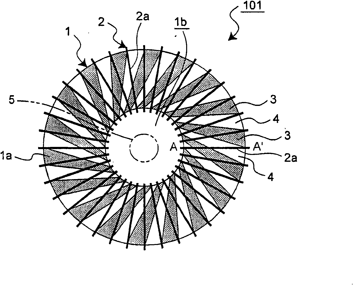
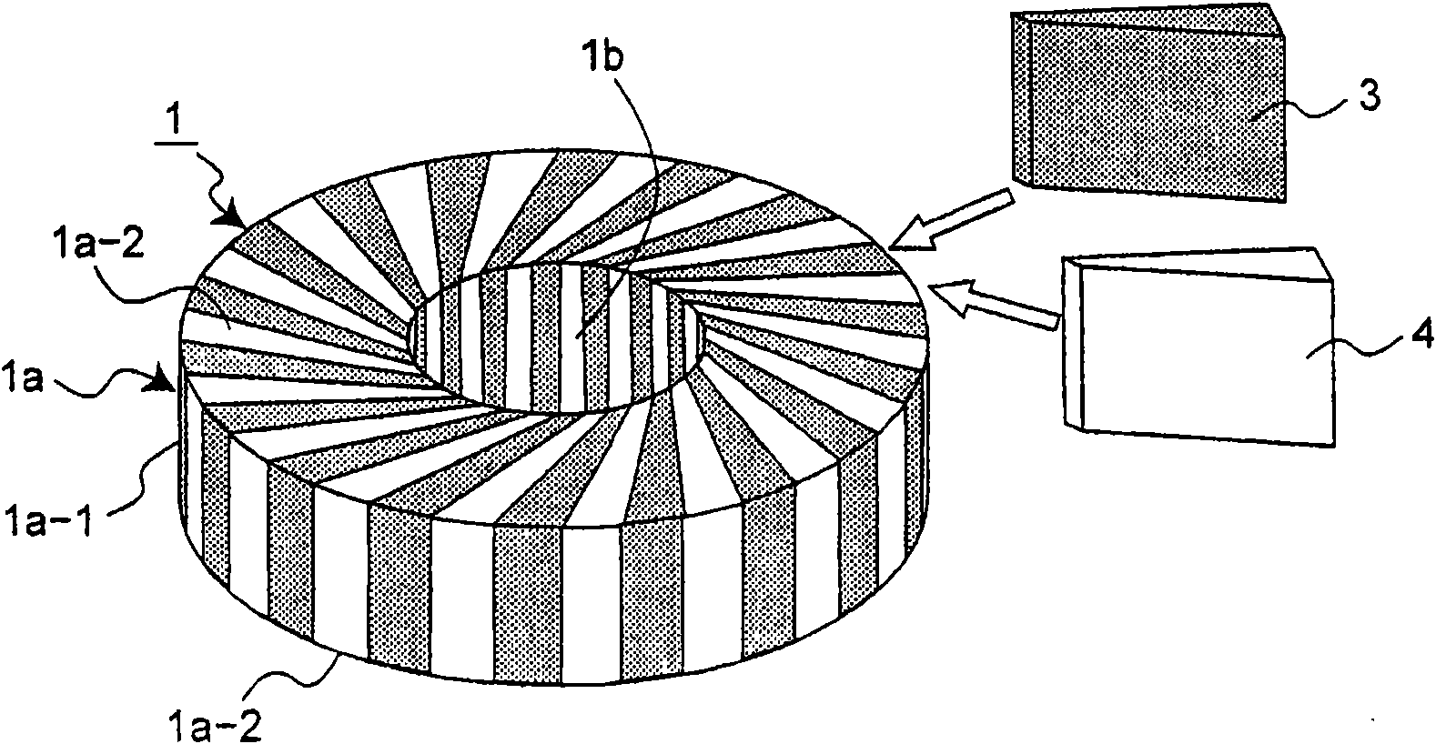
[0052] refer to Figure 1 ~ Figure 3 , Figure 4A ,as well as Figure 4B The current sensor 101 according to Embodiment 1 of the present invention will be described. Such as figure 1 As shown, the current sensor 101 includes a core 1 and a secondary winding 2 .
[0053] In this embodiment, the core part 1 has a trunk part 1a formed by cutting a pipe into an annular shape, and a through-hole formed in a central part 1b. The trunk portion 1a has a peripheral surface 1a-1 and upper and lower surfaces 1a-2. In the present embodiment, the upper and lower surfaces 1a-2 each form a flat surface, but a convex shape such as a semicircle may also be used. In the through hole, the primary conductor 5 through which the primary current as the current to be measured flows is arranged along the central portion 1b, that is, the penetrating core portion 1 .
[0054] The core 1 further has: a plurality of magnetic body parts 3 composed of a magnetic body that divides the core part 1 in th...
Embodiment approach 2
[0074] Next, refer to Figure 10 The current sensor 106 according to Embodiment 2 of the present invention will be described. In addition, in Figure 10 In FIG. 2 , only the core part constituting the current sensor 106 is shown, and the illustration of the secondary winding 2 is omitted.
[0075]In Embodiment 1 described above, the core portion 1 is constituted by one structure in which the magnetic body portion 3 and the non-magnetic body portion 4 are integrally formed. In contrast, in the current sensor 106 according to Embodiment 2, the core 1 includes a plurality of divided cores 21 and 22 , here two. Embodiment 1 differs from Embodiment 2 in this point. By combining a plurality of split cores to form one core 1, an arbitrary distribution of sensitivity coefficients can be obtained as a characteristic of the current sensor. The description above in Embodiment 1 is applicable to other configurations and modified examples of the current sensor 106 , so those descriptio...
Embodiment approach 3
[0097] Next, refer to Figure 14 as well as Figure 15 A current sensor according to Embodiment 3 of the present invention will be described. In this embodiment, the current sensor described in Embodiments 1 and 2 above is fabricated on a plated or printed wiring board having excellent shape controllability.
[0098] Figure 14 as well as Figure 15 The current sensor 107 of this embodiment is shown to be figure 1 The current sensor 101 shown is fabricated on a substrate. Of course, the forms of the above-mentioned current sensors 102 to 106 may also be fabricated on the structure described below.
[0099] The current sensor 107 includes a first winding pattern substrate 9-1, a second winding pattern substrate 9-2, and a core pattern substrate 12 sandwiched between these winding pattern substrates 9-1, 9-2. The first winding pattern substrate 9-1 is a substrate made of a non-magnetic material such as a printed wiring board, and in this example, the above-mentioned conduc...
PUM
 Abstract
Description
Claims
Application Information
 - R&D Engineer
- R&D Manager
- IP Professional
- Industry Leading Data Capabilities
- Powerful AI technology
- Patent DNA Extraction
Browse by: Latest US Patents, China's latest patents, Technical Efficacy Thesaurus, Application Domain, Technology Topic, Popular Technical Reports.
© 2024 PatSnap. All rights reserved.Legal|Privacy policy|Modern Slavery Act Transparency Statement|Sitemap|About US| Contact US: help@patsnap.com