Damage-tolerance testing method for whole wing spar of airplane
A technology of damage tolerance and test method, which is applied in the field of aircraft fatigue damage tolerance test, can solve the problems of lack of theoretical research on damage tolerance of the overall structure, insufficient understanding and grasp of regularity, and lack of special test research, etc., to achieve Reliable test data and calculation methods, saving test time and cost, and eliminating the effect of single beam distortion
- Summary
- Abstract
- Description
- Claims
- Application Information
AI Technical Summary
Problems solved by technology
Method used
Image
Examples
Embodiment 1
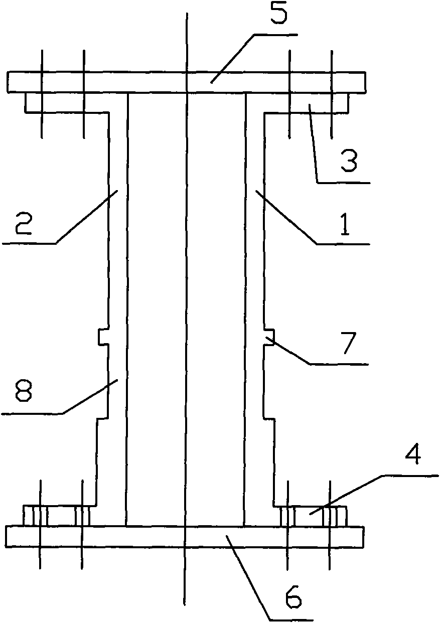
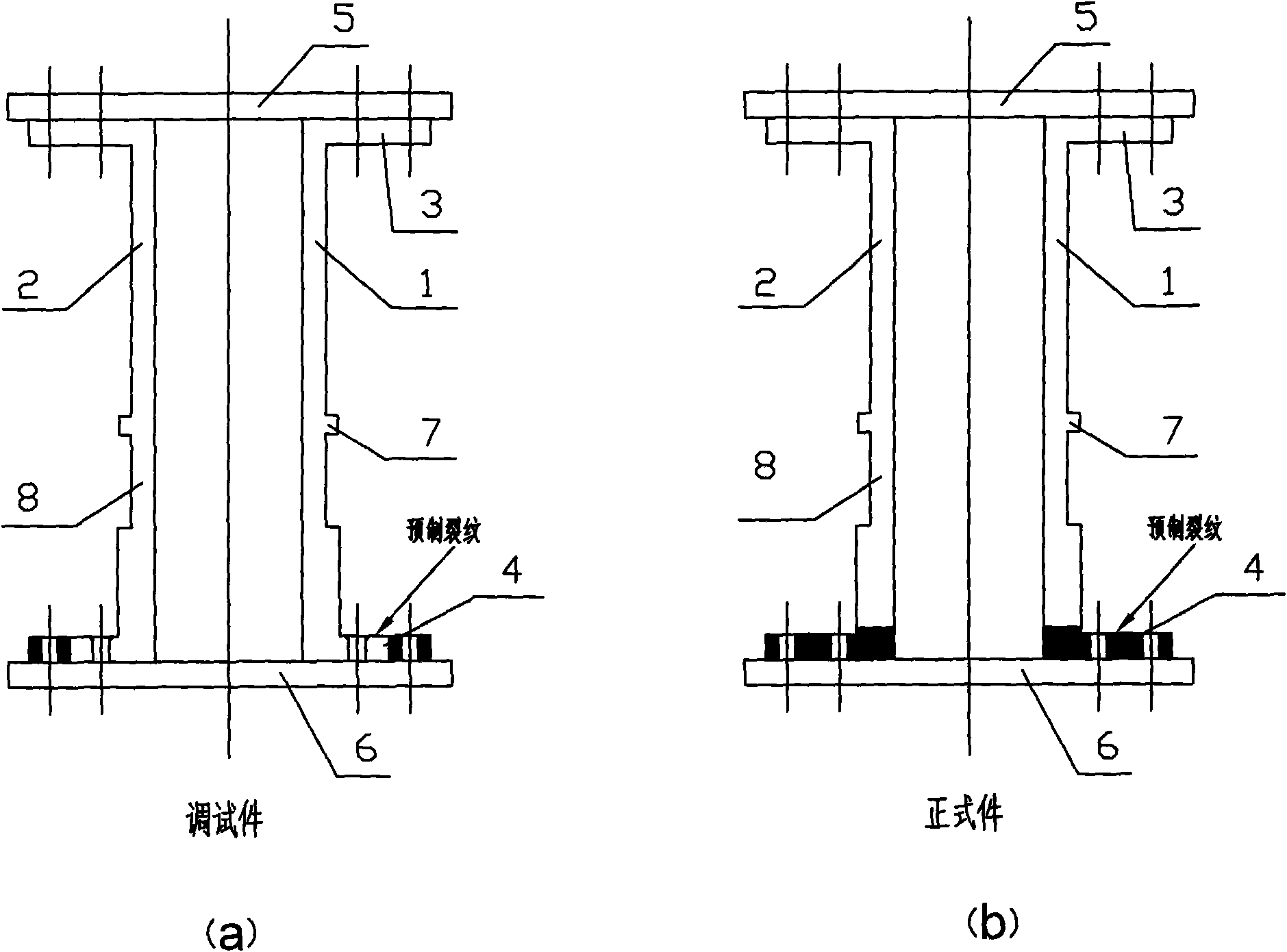
[0012] A schematic diagram of the test piece can be seen in figure 1 ; The initial prefabricated cracks of the test piece are visible figure 2 .
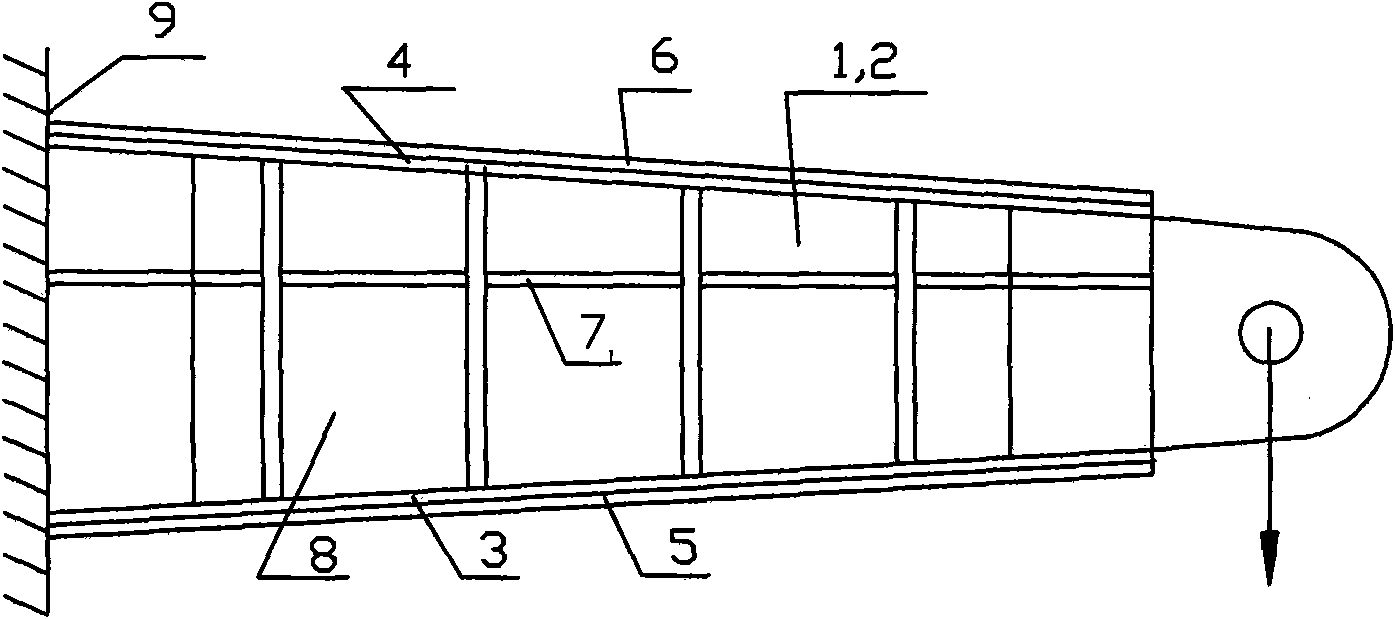
[0013] (1) Test piece design: such as figure 1 As shown, the outer dimension of the integral beam specimen is 1000×310×55mm, and the material is 7050-T7451; In order to prevent the twisting of the single-wing beam under load, the test piece adopts two integral beam test pieces 1 and 2, back to back and separated by a distance of about 30mm, and the upper and lower sides are connected by skins 5 and 6 to form a box section;
[0014] (2) Test piece installation and loading: According to the convenience of test loading, the test piece is in the form of flipping (note that the upper and lower skins defined above refer to the upper and lower skins after flipping), and the root is composed of bending load and The clamp for the shear load is connected to a steel plate with a thickness of 30mm, and then the steel plate is installed on t...
Embodiment 2
[0022] (1) Test piece design: the outer dimension of the overall beam test piece is 1500×500×55, and the material is 7050-T7451; The location of the crack relief ribs has changed. In order to prevent the twisting of the single-wing beam under load, the test piece adopts two integral beam test pieces 1 and 2, back to back and separated by a distance of about 30mm, and the upper and lower sides are connected by skins 5 and 6 to form a box section;
[0023] (2) Test piece installation and loading: According to the convenience of test loading, the test piece is in the form of flipping (note that the upper and lower skins defined above refer to the upper and lower skins after flipping), and the root is composed of bending load and The clamp for the shear load is connected to a steel plate with a thickness of 30mm, and then the steel plate is installed on the load-bearing wall 9, and the loading end is loaded through the actuator;
[0024] (3) Crack growth test: measure the crack g...
PUM
 Abstract
Description
Claims
Application Information
 - R&D
- Intellectual Property
- Life Sciences
- Materials
- Tech Scout
- Unparalleled Data Quality
- Higher Quality Content
- 60% Fewer Hallucinations
Browse by: Latest US Patents, China's latest patents, Technical Efficacy Thesaurus, Application Domain, Technology Topic, Popular Technical Reports.
© 2025 PatSnap. All rights reserved.Legal|Privacy policy|Modern Slavery Act Transparency Statement|Sitemap|About US| Contact US: help@patsnap.com


