Eureka AIR delivers breakthrough ideas for toughest innovation challenges, trusted by R&D personnel around the world.

Vortex diode

A diode, eddy current technology, applied in the direction of fluid flow, mechanical equipment, etc., can solve the problems of blockage, leakage of sealing material, wear and so on

Inactive Publication Date: 2011-05-25
ZHEJIANG UNIV
View PDF0 Cites 0 Cited by
  • Summary
  • Abstract
  • Description
  • Claims
  • Application Information

AI Technical Summary

Problems solved by technology

Traditional conveying devices such as impeller pumps are prone to wear and blockage due to the existence of moving parts, and the moving parts need to be sealed. Most of the corresponding sealing materials are easily damaged by the dilution of radioactive solutions, which may cause unsafe problems such as leakage.

Method used


Image

  • Vortex diode
  • Vortex diode
  • Vortex diode

Examples


Embodiment Construction

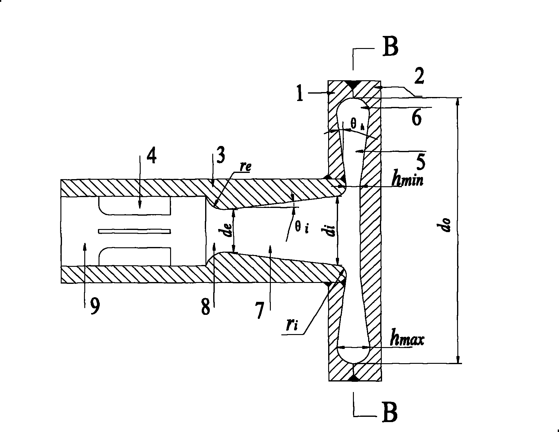
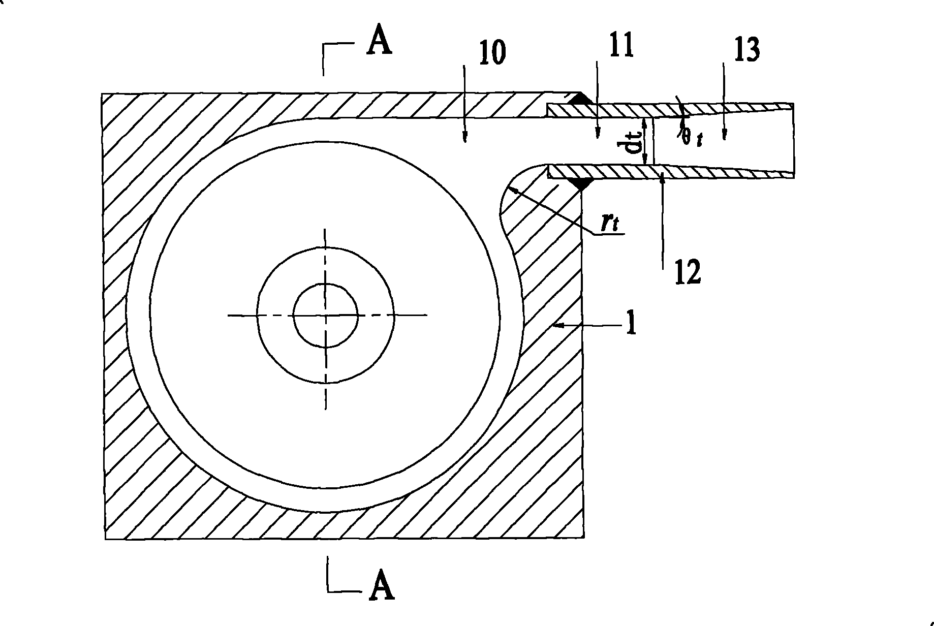
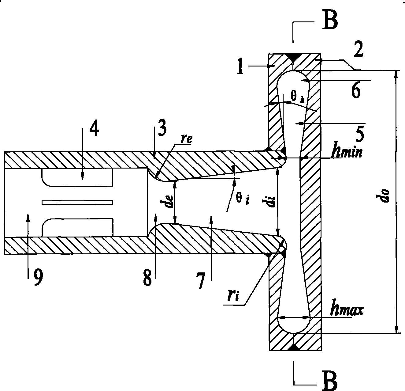
[0019] Such as figure 1 , 2 As shown, the eddy current diode includes an upper cover plate 1, a lower cover plate 2, a central tube shell 3, a guide vane 4, a vortex chamber 5, a semicircular side wall 6, a central cone tube 7, an arc shrink tube 8, and a central straight tube 9 , arc transition area 10, tangential pipe shell 12, tangential tapered pipe 13; center pipe shell 3 is divided into central tapered pipe 7, arc shrinkage pipe 8, central straight pipe 9, center pipe from bottom to top The lower end of the casing 3 is provided with an upper cover plate 1, the upper cover plate 1 is connected with the lower cover plate 2 to form a vortex chamber 5, the central straight pipe 9 is provided with a guide vane 4, and a tangential pipe casing is provided in the tangential direction of the circumference of the vortex chamber 5 12. The tangential tube housing 12 is divided into a tangential straight tube 11 and a tangential conical tube 13 from inside to outside. The junction o...


PUM


Abstract

The invention discloses a vortex diode, which comprises an upper cover plate, a lower cover plate, a central tube shell, a tangential tube shell and the like; the central tube shell is divided into a central conical tube, a circular arc shrinking tube and a central straight tube from bottom to top; the lower end of the central tube shell is connected with the upper cover plate; the upper cover plate is abutted with the lower cover plate to form a vortex cavity; the central straight pipe is provided with guide blades; the tangential tube shell is tangent to the vortex cavity on the circumference and is divided into a tangential straight tube and a tangential conical tube from inside to outside; and the joint of the tangential tube shell of the vortex cavity is a circular arc transition region. The central tube is provided with the guide blades, the tangential tubes and the central tube are respectively provided with a conical tube structure, and the vortex cavity is divergent to increase the impedance ratio of the vortex diode; and the peripheral thickness of the vortex cavity is equal to the tube diameter of the tangential straight tube, the joint of the central tube and the vortexcavity is a large chamfer angle, the joint of the tangential tubes and the vortex cavity is circular arc transition, and the impedance ration of positive flow and reverse flow is 20 to 40.

Description

technical field [0001] The present invention relates to fluid transport control devices, and more particularly to an eddy current diode. Background technique [0002] In the process of reprocessing in the nuclear industry, in order to purify and treat spent radioactive fuel, the first thing we face is the transportation of radioactive solutions. Because the spent fuel is highly radioactive, it is not suitable for staff to come into close contact with it. Therefore, it is necessary to use maintenance-free delivery equipment that can be controlled remotely for transportation. Traditional conveying devices such as impeller pumps are prone to wear and blockage due to the existence of moving parts, and the moving parts need to be sealed. Most of the corresponding sealing materials are easily damaged by the dilution of radioactive solutions, causing leakage and other unsafe problems. [0003] In the maintenance-free conveying equipment, in order to control the flow direction of t...

Claims


Application Information

Patent Timeline
Patent Type & Authority Patents(China)
IPC IPC(8): F15D1/02
Inventor 焦磊孙青军王乐勤戴维平
Owner ZHEJIANG UNIV
Why Eureka
Eureka Blog
Learn More