Acoustic waveguide horn

A sound wave and horn technology, applied in the direction of frequency/direction characteristic devices, etc., can solve the problems of chamber effect, woofer horn radiation area reduction, and poor pointing control force, etc., to increase the effective radiation area and good radiation area , to avoid the effect of the chamber effect

Active Publication Date: 2011-12-28
GUANGZHOU RUIFENG AUDIO TECH
View PDF0 Cites 0 Cited by
  • Summary
  • Abstract
  • Description
  • Claims
  • Application Information

AI Technical Summary

Problems solved by technology

However, since the opening area of ​​the treble horn mouth occupies about half of the radiating area of ​​the bass horn in this structure, if the directivity of the treble horn is to be wider and more constant or the lower limit of the working frequency is lower, the area of ​​the treble horn mouth needs to be If it is further increased, the radiation area of ​​the bass horn will be further reduced, and a chamber effect will appear, which will deteriorate the sound reinforcement quality of the bass and affect the clarity of sound reinforcement; if the opening angle or area of ​​the treble horn is reduced, The impact on the woofer will be reduced, but its directional control will be worse; if the opening angle or area of ​​the treble horn is large enough, and the woofer is not affected, the woofer can only be further increased , this will inevitably increase the overall volume of the combined horn, which limits the scope of application of the combined horn

Method used


Image

  • Acoustic waveguide horn
  • Acoustic waveguide horn
  • Acoustic waveguide horn

Examples


Embodiment Construction

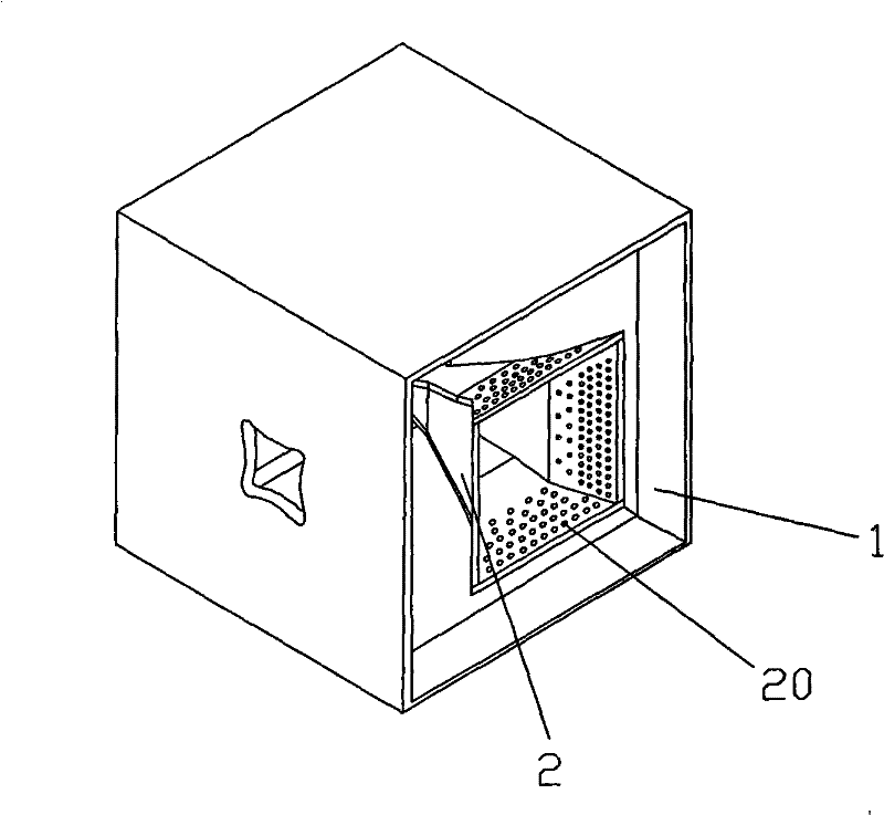
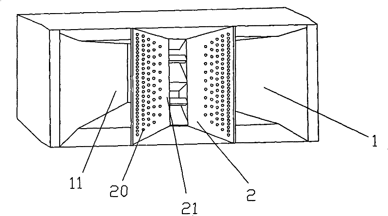
[0016] refer to Figures 1 to 4 , a sound-transmitting waveguide horn, comprising a bass horn 1 and a treble horn 2, the rear end of the bass horn is provided with a bass driver 3, the rear end of the treble horn is provided with a treble driver 4, and the treble horn 2 is installed in the cavity of the bass horn 11, the wall of the tweeter horn 2 is provided with through holes 20, when in use, the low sound is transmitted through these through holes, increasing the effective radiation area of ​​the bass horn.

[0017] The through hole 20 communicates with the woofer horn cavity 11 and the tweeter horn cavity 21 .

[0018] The through holes 20 are densely distributed on the side of the opening edge of the tweeter horn 3 that is farther away from the opening edge of the tweeter horn 2 .

[0019] The geometric size of the through hole 20 near the edge of the two openings of the tweeter horn is greater than that of the through hole far from the edge of the two openings of the tw...


PUM


Abstract

The invention discloses a sound-transmitting waveguide horn. It includes a bass horn and a treble horn, the bass driver is provided at the rear end of the bass horn, the treble driver is provided at the rear end of the treble horn, the treble horn is installed in the cavity of the bass horn, and a through hole is provided on the wall of the treble horn . Because there are through holes on the opening wall of the treble horn, the bass sound waves can be radiated through these holes, increasing the effective radiation area of ​​the bass horn, avoiding the chamber effect in the bass horn cavity, and ensuring the direction control ability and working frequency of the treble horn The lower limit can also make the bass horn have a good radiation area without increasing the volume of the bass horn, which increases the application range of the horn.

Description

technical field [0001] The invention relates to an electroacoustic equipment, in particular to a sound-transmitting waveguide horn. Background technique [0002] The horn speaker is composed of a horn and a driver. Because of its high sound transmission efficiency and strong directional control, it is widely used in sound reinforcement systems in various occasions, and it is also used in conventional speakers. Among them, the treble horn and the treble driver used for treble sound reinforcement form the treble horn speaker, and the woofer horn and the bass driver used for bass sound reinforcement form the woofer horn speaker. [0003] The combined horn is a composite horn composed of a treble horn and a woofer. In order to reduce the volume of this composite horn, the treble horn and the treble driver are installed in the front of the woofer. However, since the opening area of ​​the treble horn mouth occupies about half of the radiating area of ​​the bass horn in this struc...

Claims


Application Information

Patent Timeline
Patent Type & Authority Patents(China)
IPC IPC(8): H04R1/30
Inventor 胡秉奇徐运虎
Owner GUANGZHOU RUIFENG AUDIO TECH
Why Eureka
Try Eureka