
Dual-redundancy switch reluctance motor

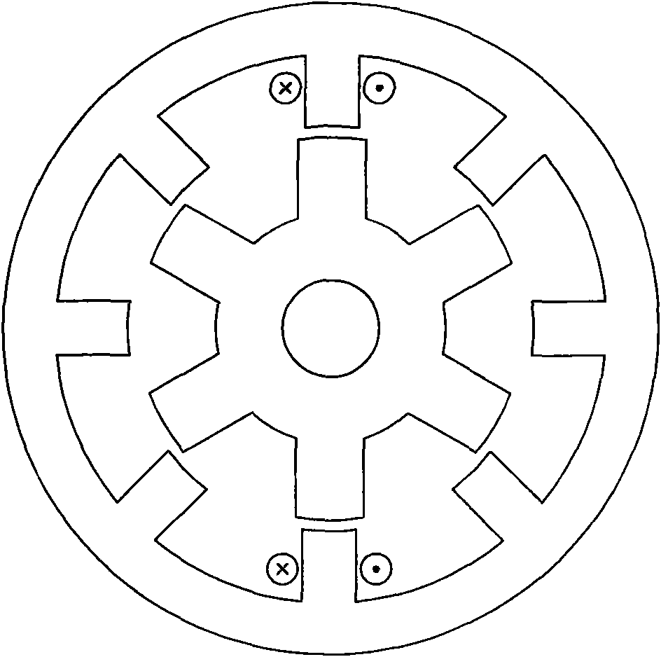
A technology of switched reluctance motor and double redundancy, which is applied to the static parts of the magnetic circuit, the rotating parts of the magnetic circuit, the shape/style/structure of the magnetic circuit, etc., which can solve the problems of low reliability and achieve improved efficiency and improved Reliable performance and the effect of improving system performance

Inactive Publication Date: 2009-10-07
HARBIN INST OF TECH
View PDF0 Cites 7 Cited by
  • Summary
  • Abstract
  • Description
  • Claims
  • Application Information

AI Technical Summary

Problems solved by technology

[0004] In order to solve the problem of low reliability caused by only one set of windings in the existing switched reluctance motor, the present invention provides a double redundancy switched reluctance motor

Method used


Image

  • Dual-redundancy switch reluctance motor
  • Dual-redundancy switch reluctance motor
  • Dual-redundancy switch reluctance motor

Examples


Embodiment Construction

[0011] The double-redundancy switched reluctance motor described in this embodiment includes an air gap 1, a rotor core 6, and a stator core 4. It also includes two sets of three-phase windings. There are 10 rotor teeth on the rotor core 6, and the stator core 4 There are 12 stator teeth on it, and the same-phase windings of each set of three-phase windings are symmetrically wound on the stator teeth of the stator core 4, and form magnetic fluxes in the same direction. Two in-phase windings belonging to two sets of three-phase windings on two parallel stator teeth form magnetic fluxes in opposite directions, forming a short magnetic circuit structure.

[0012] Both the stator core 4 and the rotor core 6 of the motor in this embodiment have a salient pole structure.

[0013] The arrangement order of the two sets of three-phase windings on the stator teeth is:

[0014] a1→a2→c1→c2→b1→b2→a1→a2→c1→c2→b1→b2.

[0015] The arrangement order of the two sets of three-phase windings o...


PUM


Abstract

A dual-redundancy switch reluctance motor relates to the motor field and solves the problem of low reliability of the existing switch reluctance motors caused by only one set of winding available. The motor of the invention comprises two sets of three-phase windings. A rotor core has 10 rotor teeth; a stator core has 12 stator teeth; the in-phase winding of each set of three-phase winding is wound on the stator teeth of the stator core symmetrically and forms magnetic flux of the same direction; the stator teeth wound by the in-phase winding are mutually parallel, and two in-phase windings respectively wound on two adjacent parallel stator teeth form magnetic flux of reverse direction to form a short magnetic structure. The windings of the motor are mutually independent; when one phase or a plurality of phases of windings break down, the motor works with derating, without affecting the functions of the motor, thus realizing the redundancy of the switch reluctance motor and improving the reliability of the motor and the control system thereof. The motor has favorable application prospect in space flight, aviation, elevators, household appliances, etc.

Description

technical field [0001] The invention relates to the field of motors, in particular to a switched reluctance motor. Background technique [0002] Existing switched reluctance motors such as those shown in the accompanying drawings figure 1 As shown, the stator and rotor of the motor are salient pole structures. By sequentially energizing the stator field windings, the stator poles interact with the rotor poles to generate torque. Since there are neither windings nor permanent magnets on the rotor, the structure of the motor is simple and the operation is reliable. However, since the motor has only one set of windings, when one of the windings fails, the system will stop working, which greatly affects the reliability of the system. [0003] See attached figure in the manual figure 2 , which illustrates the structure of the existing switched reluctance motor. The stator has three-phase windings, and the same-phase windings are connected in series. The number of stator teet...

Claims


Application Information

Patent Timeline
IPC IPC(8): H02K3/12H02K3/28H02K1/14H02K1/24
Inventor 吴红星贵献国寇宝泉侯云鹏刘奉海
Owner HARBIN INST OF TECH
Learn More