Variable angular momentum engine

An angular momentum and engine technology, applied in the direction of engine control, machine/engine, mechanical equipment, etc., can solve problems such as minimum speed limit, engine efficiency drop, engine speed reduction, etc., to achieve good environmental performance, fuel saving, reliable operation. Effect

Inactive Publication Date: 2009-10-07
靳北彪
View PDF0 Cites 2 Cited by
  • Summary
  • Abstract
  • Description
  • Claims
  • Application Information

AI Technical Summary

Problems solved by technology

The traditional engine reduces the speed of the engine by reducing the amount of oil injected each time, which causes the combustion state of the engine to deviate far from the optimal state at low speeds, and the efficiency of the engine also drops significantly
In addition, when the engine is at idle speed, the inertia matching of the traditional engine is realized through the flywheel with non-adjustable inertia, so its minimum speed is limited and cannot be reduced to a very low speed.
Because the flywheel of the engine cannot store enough kinetic energy to maintain the normal operation of the engine at extremely low speeds, the current engine idle speed can only be more than a few hundred revolutions
It can be seen from this that the efficiency of the traditional engine is low at low speed, and a higher speed is required to maintain the normal operation of the engine at idle speed.

Method used


Image

  • Variable angular momentum engine
  • Variable angular momentum engine
  • Variable angular momentum engine

Examples


Embodiment Construction

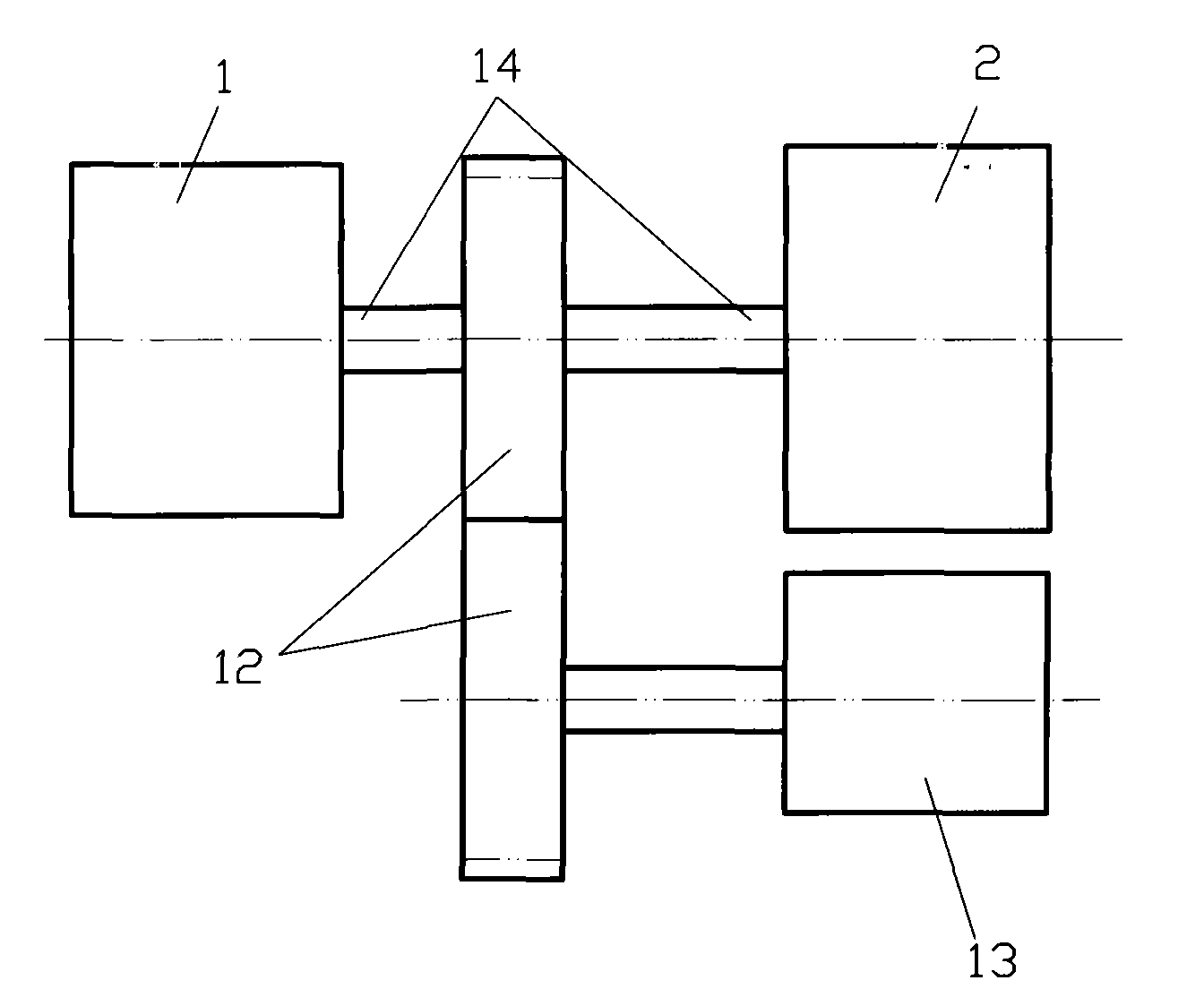
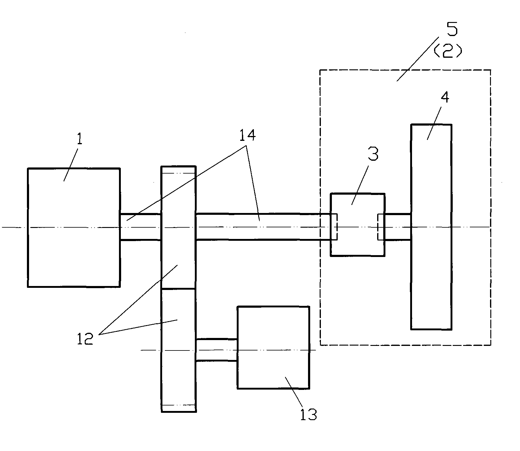
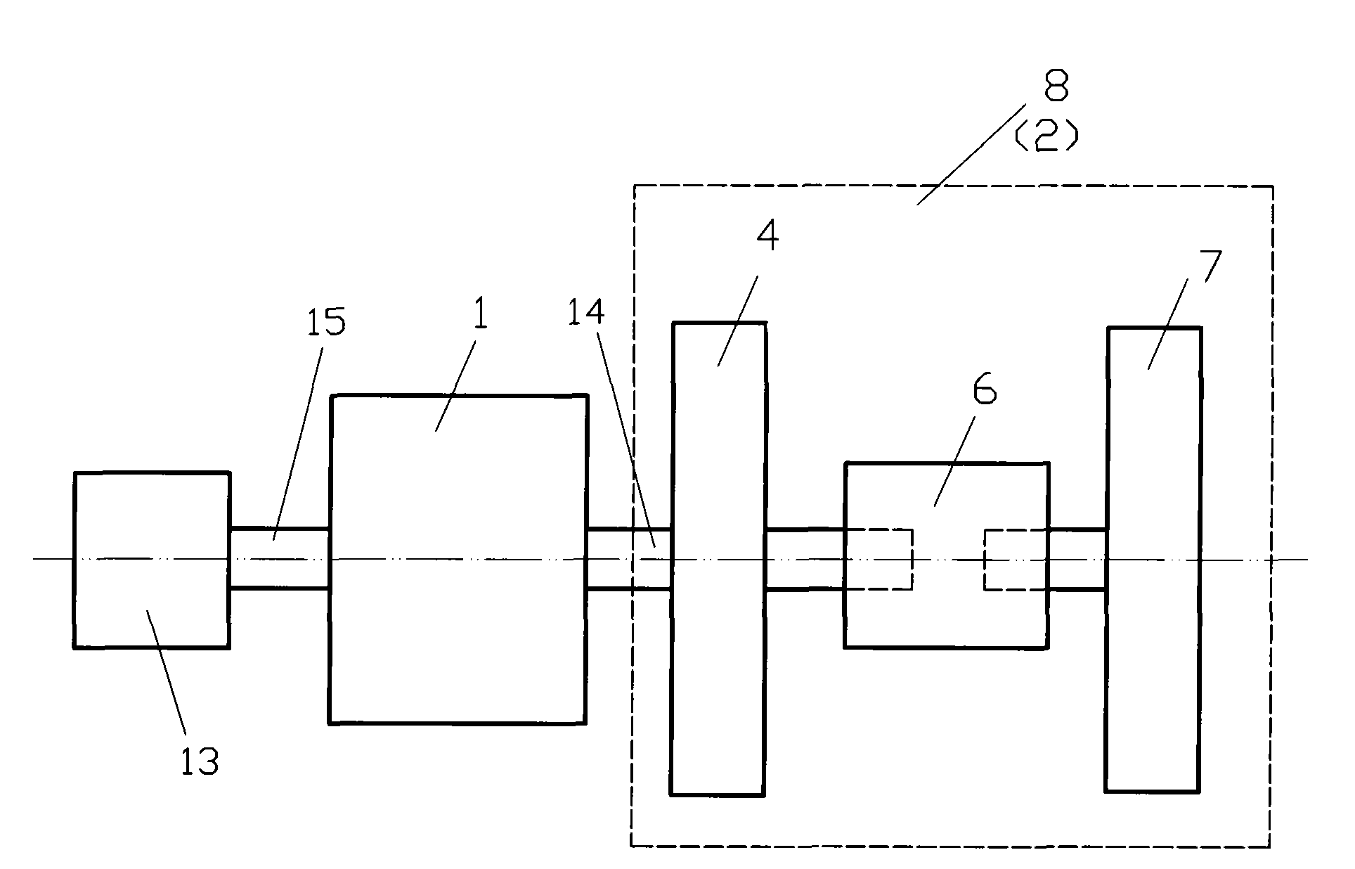
[0020] Figure number

[0021] 1. Engine 2. Angular momentum adjustable mechanism 3. Transmission device

[0022] 4. Flywheel 5. Angular momentum adjustable mechanism with adjustable speed 6. Clutch device

[0023] 7. Inertia body 8. Axial inertia adjustable angular momentum adjustable mechanism

[0024] 9. Radial movable inertial body 10. Radial inertia adjustable angular momentum adjustable mechanism

[0025] 11. Load response control device 12. Gear set 13. Load

[0026] 14. PTO shaft 15. Another PTO shaft 16. Artificially expected load information

[0027] The present invention is described in detail below in conjunction with accompanying drawing and specific embodiment:

[0028] Please refer to figure 1 , 2 The variable angular momentum motor shown in , 3, 4, 5 and 6 includes: an engine 1 , the power output shaft 14 of the engine 1 is connected with the angular momentum adjustable mechanism 2 .

[0029] Please refer to figure 2 In the shown variable angular moment...


PUM


Abstract

The invention discloses a variable angular momentum engine, comprising an engine, wherein the power output shaft of the engine is connected with an angular momentum adjustable mechanism. The variable angular momentum engine realizes the matching of the engine under different rotation speed conditions by adjusting the angular momentum of the angular momentum adjustable mechanism according to the practical load of the engine or the load expected artificially, and has the advantages of simple structure, reliable operation, fuel-saving, environment-protection and good performance.

Description

technical field [0001] The invention relates to the field of engines. Background technique [0002] There will always be load changes during the running of the engine, and the load changes are directly expressed as changes in the engine speed. Traditional engines reduce the speed of the engine by reducing the amount of oil injected each time, which causes the combustion state of the engine to deviate far from the optimal state at low speeds, and the efficiency of the engine also drops significantly thereupon. In addition, when the engine is at idle speed, the inertia matching of the traditional engine is realized through the flywheel with non-adjustable inertia, so its minimum speed is limited and cannot be reduced to a very low level. Because the flywheel of the engine cannot store enough kinetic energy to maintain the normal operation of the engine at extremely low speeds, the current engine idle speed can only be above a few hundred revolutions. It can be seen from this...

Claims


Application Information

Patent Timeline
IPC IPC(8): F02D31/00
Inventor 靳北彪
Owner 靳北彪
Why Eureka
Try Eureka