Fracture traction device used for train berth

A traction device and sleeper technology, applied in the field of human medical devices, can solve the problems of large space occupation, delayed treatment, secondary injury, etc., and achieve the effects of small physical space, convenient installation, and convenient adjustment.

Inactive Publication Date: 2011-09-28
THE SECOND AFFILIATED HOSPITAL ARMY MEDICAL UNIV
View PDF0 Cites 0 Cited by
  • Summary
  • Abstract
  • Description
  • Claims
  • Application Information

AI Technical Summary

Problems solved by technology

[0003] In emergency rescue and emergency operations, it is necessary to transfer the wounded urgently and carry out necessary treatment during the transfer. However, there is currently no traction device for lower limbs suitable for use in trains, while the orthopedic traction bed and Brown's frame are commonly used in hospitals. , it occupies a large space, and the space between the lower berth and the middle berth of the non-train sleeper berth can accommodate it, so it is difficult to put it into use on the train, which brings great inconvenience to the train to transport the fractured patient, and is not conducive to the health of the patient. Recovery, delayed treatment and easy to cause secondary injury, and increase the pain of the wounded, causing great difficulties to the rescue work, affecting the efficiency of mobilizing and allocating health resources
[0004] In the 5.12 Wenchuan Earthquake in 2008, the train transfer of the wounded and sick, due to the lack of such a traction device for fracture injuries used in train sleepers, resulted in a large proportion of secondary injuries in the wounded and sick with fractures, which increased the pain of the wounded and worsened their injuries. Bringing more difficulties to medical treatment and rehabilitation of the wounded

Method used


Image

  • Fracture traction device used for train berth
  • Fracture traction device used for train berth
  • Fracture traction device used for train berth

Examples


Embodiment Construction

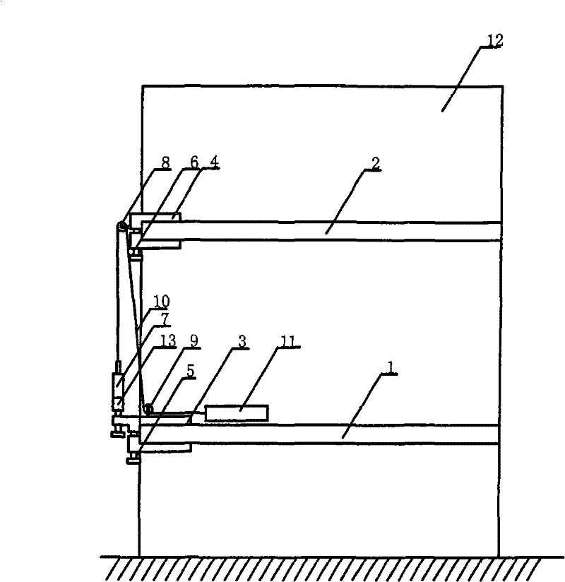
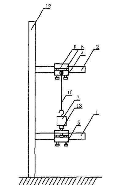
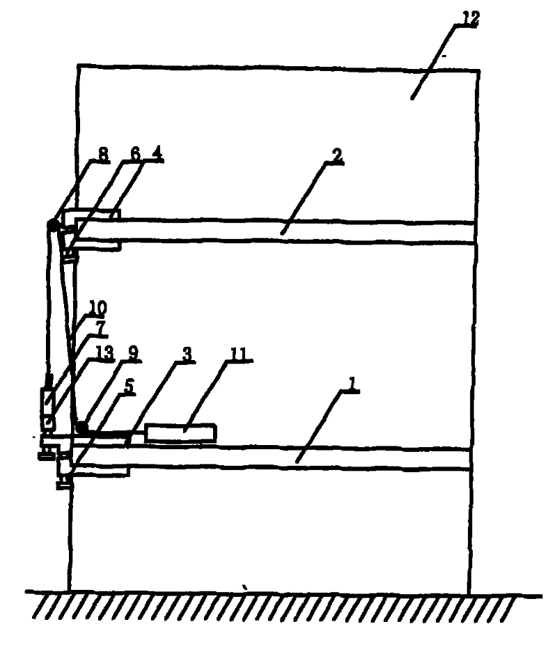
[0017] Such as figure 1 , figure 2 As shown, a fracture injury traction device used in a train sleeper of the present invention includes a lower splint fixing device 3, an upper splint fixing device 4, a lower fastening bolt 5, an upper fastening bolt 6, an adjustable traction device 13, a number of Visible tension meter 7, upper fixed pulley 8, lower fixed pulley 9, traction rope 10, lower fastening bolt 5 fixes the lower splint fixing device 3 on the bed edge of the lower bunk 1, and the upper fastening bolt 6 fixes the upper splint fixing device 4 on the middle bunk 2 On the bed edge, the upper fixed pulley 8 is fixed on the upper splint fixing device 4, the lower fixed pulley 9 is fixed on the lower splint fixing device 3, the adjustable traction device 12 is connected to the digital display tension meter 7, and the digital display tension meter 7 is connected to the traction rope 10. The traction rope 10 passes through the upper fixed pulley 8 and the lower fixed pulley 9...


PUM


Abstract

The invention relates to a medical instrument for human, especially a fracture traction device used for train berth, comprising a lower splint immobilization device, an upper splint immobilization device, a lower fastening bolt, an upper fastening bolt, a device capable of adjusting traction force, a traction dynamometer, an upper fixed pulley, a lower fixed pulley, a traction rope. The lower splint immobilization device is immobilized on the lower berth edge by the lower fastening bolt and the upper splint immobilization device is immobilized on the middle berth edge by the upper fastening bolt and the upper fixed pulley is fixed on the upper splint immobilization device and the lower fixed pulley is fixed on the lower splint immobilization device and the device capable of adjusting traction force is connected with the dynamometer and the dynamometer is connected with the traction rope and the traction rope passes through firstly the upper fixed pulley and then the lower fixed pulley and the end of the traction rope is connected with the traction rope. The fracture traction device has features of convenient installation, less space usage and ability of realizing traction of the patient limbs or head neck bone fracture on the train berth.

Description

Technical field [0001] The invention relates to a medical device for the human body, in particular to a fracture injury traction device used in a train sleeper. Background technique [0002] Traction is often used for fracture injuries such as femoral fractures and pelvic fractures that move up significantly on one side. Because of the strong muscle traction around, the alignment of the fracture cannot be maintained with plaster or small splints after manual reduction, and continuous traction must be used to overcome the muscles Contraction, maintenance for a period of time before using external fixation, the role of fracture injury traction is to completely brake, maintain the position after reduction, reduce swelling, pain, and avoid secondary injury. [0003] In rescue and emergency operations, the wounded need to be transferred urgently, and necessary treatments should be carried out during the transfer and transportation. However, there is currently no lower limb traction devi...

Claims


Application Information

Patent Timeline
Patent Type & Authority Patents(China)
IPC IPC(8): A61F5/045B61D31/00
Inventor 陈渝孙汉军靖剑波
Owner THE SECOND AFFILIATED HOSPITAL ARMY MEDICAL UNIV
Why Eureka
Try Eureka