Earthquake recovery apparatus for elevator
An elevator and earthquake technology, applied in transportation and packaging, elevators, etc., can solve problems such as the expansion of elevator damage
- Summary
- Abstract
- Description
- Claims
- Application Information
AI Technical Summary
Problems solved by technology
Method used
Image
Examples
Embodiment approach 1
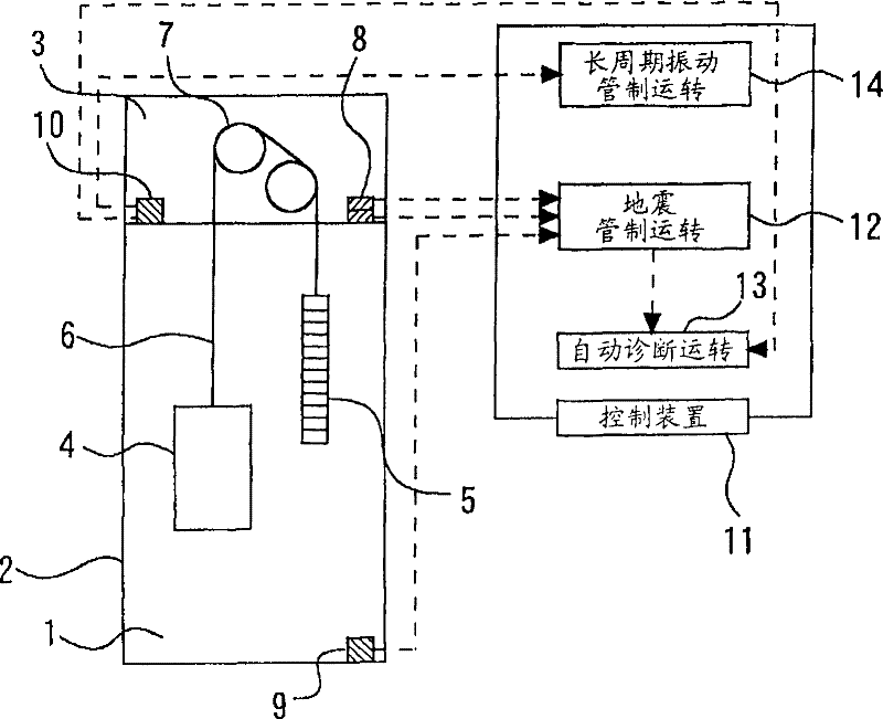
[0029] figure 1 It is a block diagram showing the earthquake recovery device for an elevator according to Embodiment 1 of the present invention. exist figure 1 Among them, 1 represents the elevator shaft installed in the building 2, and 3 represents the elevator machine room installed above the shaft 1. 4 represents the car that lifts in the hoistway 1, 5 represents the counterweight that lifts in the hoistway 1 and the car 4 in opposite directions, and 6 represents the main rope that hangs the car 4 and the counterweight 5 in the manner of hanging bottles. Reference numeral 7 denotes a driving sheave of a traction machine provided in the machine room 3 around which a part of the main rope 6 is wound.
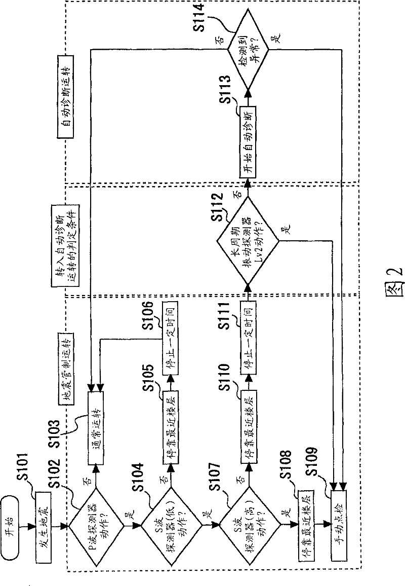
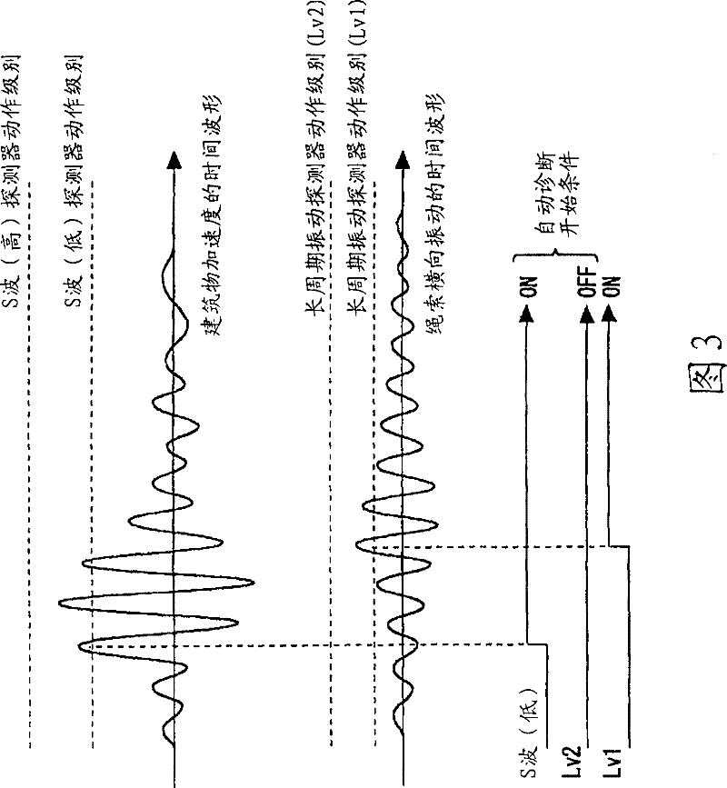
[0030] 8 represents the accelerometer, that is, the S-wave detector, installed in the machine room 3, which is used to detect the lateral shaking generated by the building 2. In this S-wave detector 8, the acceleration level of the lateral vibration of the building correspon...
Embodiment approach 2
[0052] Figure 5 It is a flowchart showing the operation of the earthquake recovery device for elevators according to Embodiment 2 of the present invention. In Embodiment 1, the following situation has been described. The detection level of the long-period vibration detector 10 is set to two levels (low level (Lv1), high-level level (Lv2)). When a high-level (Lv2) rope swing amount is detected, the transition to the automatic diagnosis operation is not performed. In this embodiment, a case will be described in which the running speed of the elevator during the diagnostic operation (hereinafter also referred to as "diagnostic speed") is changed based on the amount of rope wobble detected by the rope wobble detection device during the automatic diagnostic operation. ).
[0053] Specifically, for the long-period vibration detector 10, the levels of the amount of lateral shaking of the rope are set to multiple levels. And the long-period vibration detector 10 operates by detect...
Embodiment approach 3
[0064] Image 6 It is a flowchart showing the operation of the earthquake recovery device for elevators according to Embodiment 3 of the present invention. In Embodiment 2, the case where the diagnosis speed is changed according to the amount of rope lateral vibration detected by the long-period vibration detector 10 when performing the automatic diagnosis operation was described. In the present embodiment, a case will be described in which the operation content (diagnostic content) of the diagnostic operation is changed based on the amount of rope wobble detected by the rope wobble detection device when the automatic diagnosis operation is performed.
[0065] Specifically, as in the second embodiment, the long-period vibration detector 10 sets the levels of the amount of rope lateral vibration to multiple levels, and the long-period vibration detector 10 outputs predetermined operation signals corresponding to the respective levels.
[0066] exist Image 6 In the figure, th...
PUM
 Abstract
Description
Claims
Application Information
 - R&D Engineer
- R&D Manager
- IP Professional
- Industry Leading Data Capabilities
- Powerful AI technology
- Patent DNA Extraction
Browse by: Latest US Patents, China's latest patents, Technical Efficacy Thesaurus, Application Domain, Technology Topic, Popular Technical Reports.
© 2024 PatSnap. All rights reserved.Legal|Privacy policy|Modern Slavery Act Transparency Statement|Sitemap|About US| Contact US: help@patsnap.com


