
Quantum vacuum energy extraction

An energy and vacuum technology used in output power conversion devices, electrical components, generators/motors, etc.

Inactive Publication Date: 2009-09-16
JOVION CORP
View PDF0 Cites 2 Cited by
  • Summary
  • Abstract
  • Description
  • Claims
  • Application Information

AI Technical Summary

Problems solved by technology

Yes, the oceans are being depleted by this, but with no real consequences

Method used


Image

  • Quantum vacuum energy extraction
  • Quantum vacuum energy extraction
  • Quantum vacuum energy extraction

Examples


Embodiment Construction

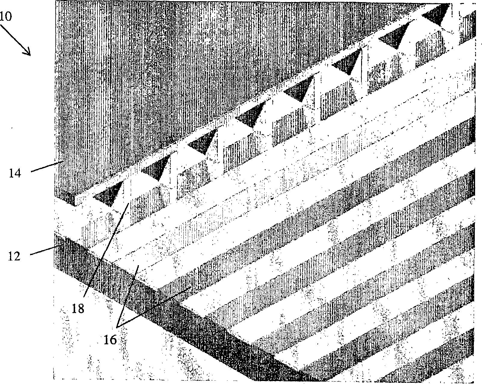
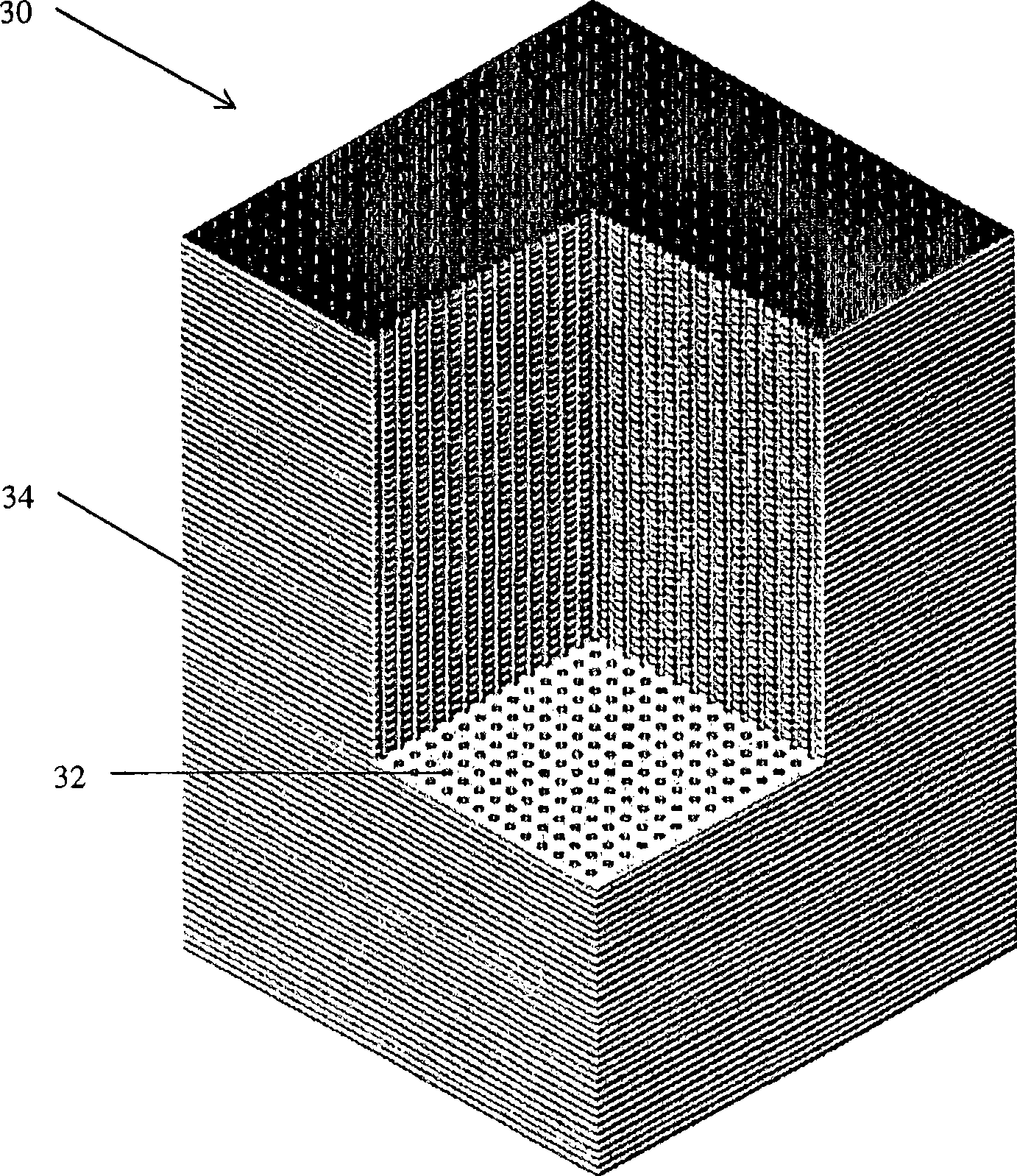
[0052] The first implementation of this concept utilizes a Casimir cavity consisting of a volume through which air flows in and out, and which appears on an atomic scale to be bounded by parallel plates of conductive material where the dimensions of the plates are much greater than the plate spacing; or where the volume appears as an area bounded by cylinders of conductive material where the length of the cylinder is much greater than its diameter. Applicant states that other forms of Casimir cavities can produce similar effects and that the term Casimir cavity will be used to denote any volume capable of mode suppression of the zero point region. A necessary condition is that the mode suppression capabilities of a Casimir cavity be matched to the electron energy levels in such a way that the electron energy levels inside and outside the cavity differ significantly.

[0053] These examples demonstrate the following concepts:

[0054] A method comprising: (a) using a device co...


PUM


Abstract

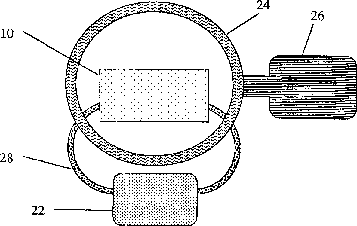
A system (fig 2) is disclosed for converting energy from the electromagnetic quantum vacuum available at any point in the universe to usable energy in the form of heat, electricity, mechanical energy or other forms of power. Mode suppression of electromagnetic quantum vacuum radiation, known to result in the emission of energy, takes place in Casimir cavities (10). When atoms enter into suitable micro Casimir cavities a decrease in the orbital energy of electrons in atoms will thus occur. Such energy is captured by the claimed devices (24,26).

Description

Background of the invention [0001] Max Planck introduced the concept of zero-point energy in 1912. This idea was subsequently investigated by Alber Einstein and Otto Stern in 1913, and in 1916, Walther Nernst proposed that the universe is filled with zero-point energy. The modern field of stochastic electrodynamics is based on these ideas. [0002] Meanwhile, the structure and stability of atoms remains a mystery. The Rutherford model of the atom is based on the analysis of the motion of the planets (electrons) around the sun (the nucleus). But this is not feasible. Orbiting electrons emit Larmor rays, lose energy rapidly and thus spiral into nuclei on timescales of less than a trillionth of a second, making it impossible to assume a stable state. Known today within stochastic electrodynamics (SED) theory is one possible approach involving the absorption of zero-point energy. Boyer demonstrated in 1975 that the simplest possible atom and atomic form, the hydrogen atom in ...

Claims


Application Information

Patent Timeline
Patent Type & Authority Applications(China)
IPC IPC(8): H02M1/00
CPCH02N11/008H02N11/002
Inventor B·海施G·摩德尔
Owner JOVION CORP
Learn More