Method for measuring hematocrit value of blood sample, method for measuring concentration of analyte in blood sample, sensor chip and sensor unit
A technology of hematocrit and sensor chip, applied in the field of determination of hematocrit value of blood sample, concentration of analyte in blood sample, sensor chip and sensor unit, can solve the problem of inability to stably measure Hct value, redox Increased current amplitude fluctuations, etc.
- Summary
- Abstract
- Description
- Claims
- Application Information
AI Technical Summary
Problems solved by technology
Method used
Image
Examples
Embodiment 1
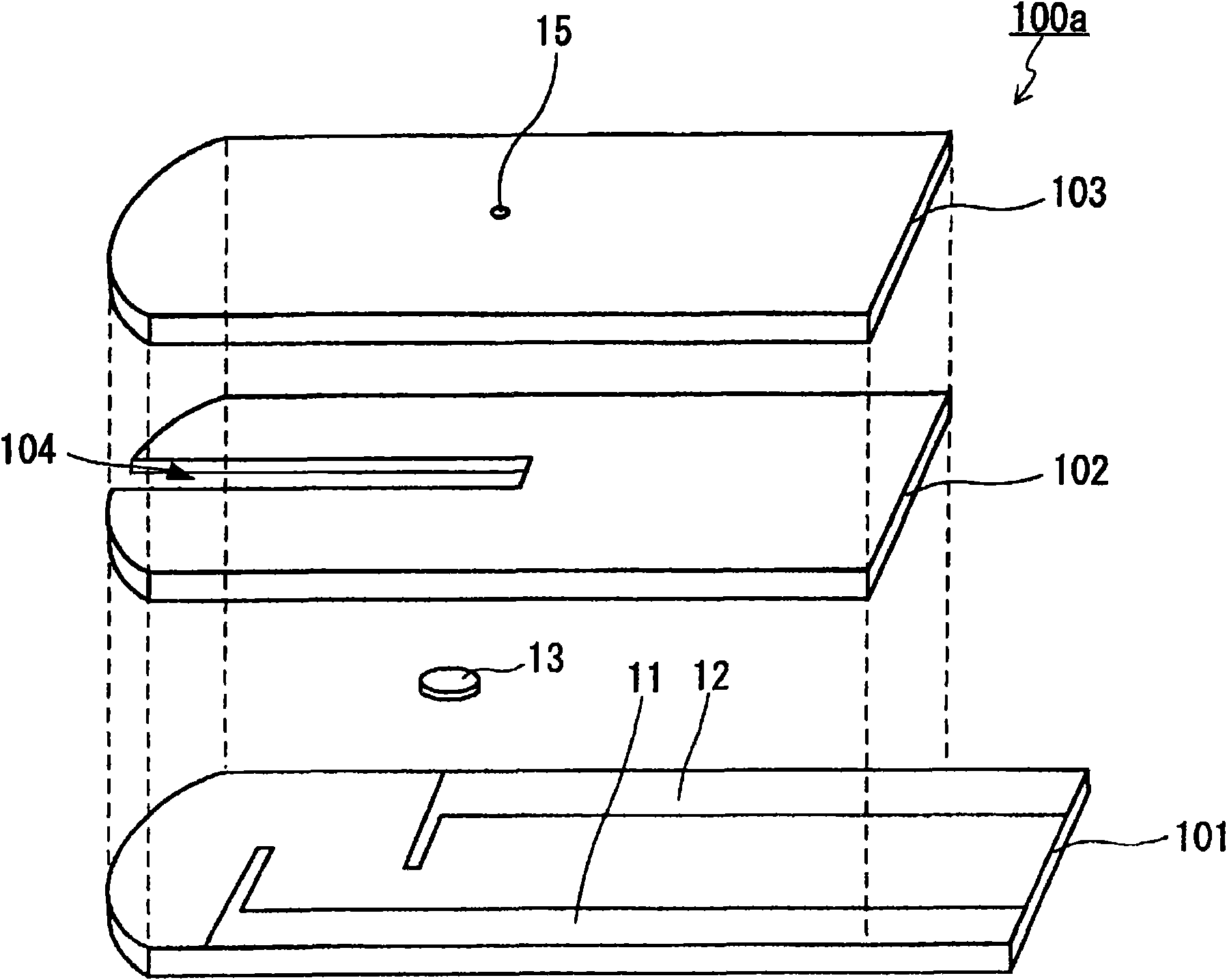
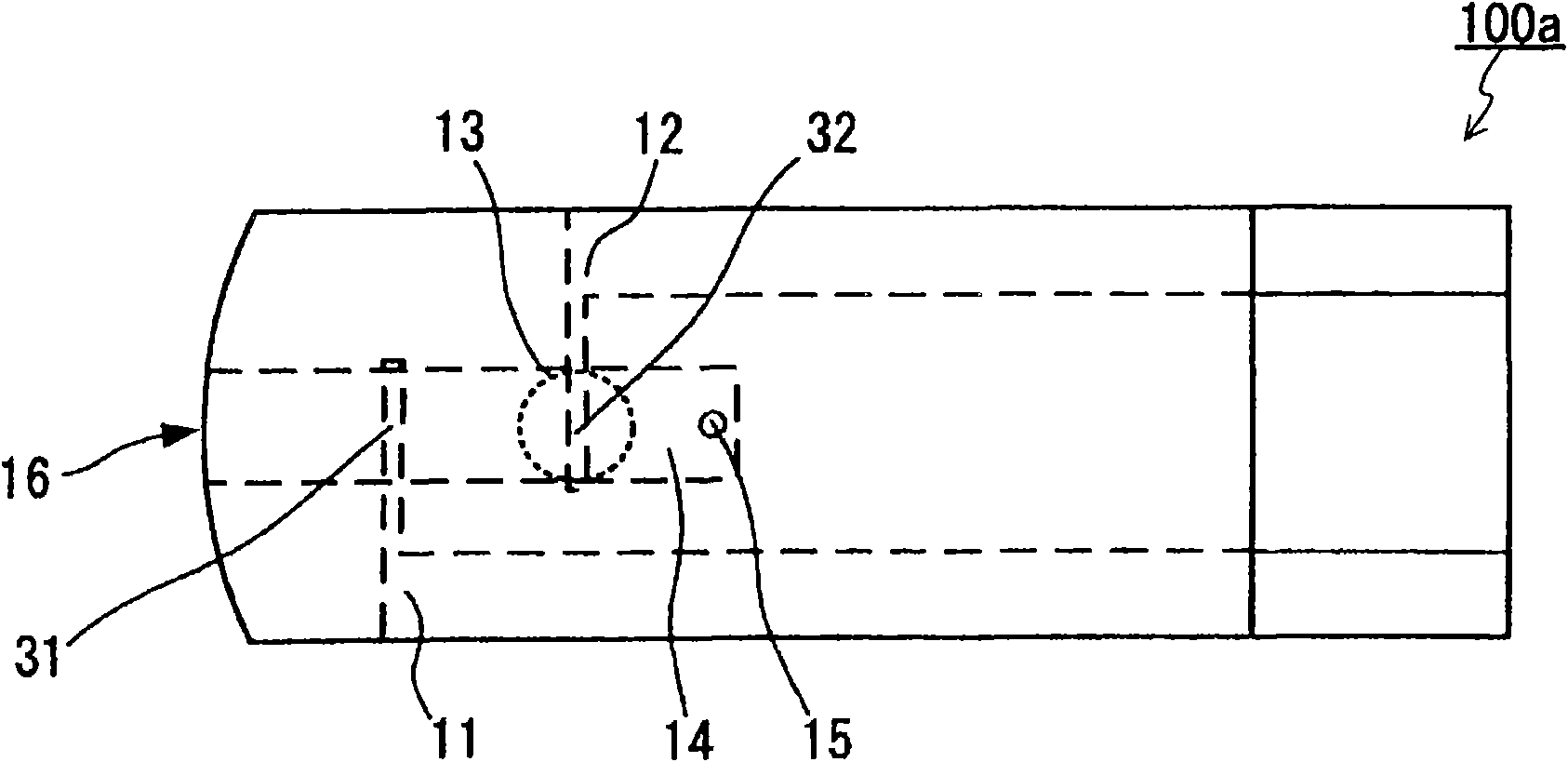
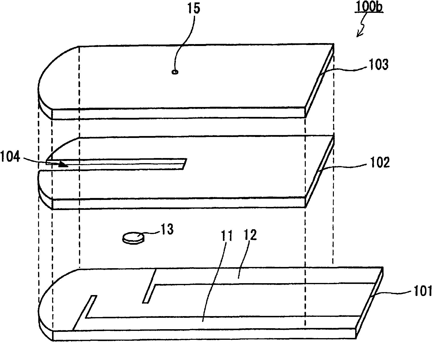
[0142] A sensor chip A for Hct value measurement was produced. The electrode cores of the working electrode and the counter electrode are made of silver. Using a spacer with a thickness of 100 μm, a blood sample holding portion with a volume of 0.8 microliter (μL) was formed. The effective areas of the active pole and the opposite pole in the blood sample holding part are 1.0mm respectively 2 , 1.8mm 2 , the closest distance between the active pole and the opposite pole is 2.4mm. The surface of the working pole facing the blood sample holding part is the surface of the electrode core body of the working pole. The surface of the counter electrode facing the blood sample holding portion is the surface of a base layer formed of a carboxymethylcellulose (CMC) film disposed on the electrode core of the counter electrode. Regarding the base layer, 0.25% by mass of CMC aqueous solution (manufactured by Daiichi Kogyo Co., Ltd.) was coated on the surface of the electrode core of th...
Embodiment 2
[0148] A sensor chip was produced in the same manner as in Example 1 except that carbon paste (manufactured by Achison Co., Ltd.) was used to form the electrode core of the counter electrode. The above-mentioned three kinds of blood samples are introduced into the blood sample holding parts of different sensor chips, and when the active pole is shown as positive pole and the opposite pole is shown as negative pole, a voltage of 3.0 V or less is applied between the two electrodes, and the voltage at the working pole is measured. and the response current flowing between the opposite poles. The measurement results of the response current are shown in Figures 14-23 of the graph. As shown in each graph, with the sensor chip of Example 2, when expressed in the same manner as above, even if a voltage of 3.0 V or less is applied between both electrodes, a stable and clear signal can be obtained immediately after the voltage application starts. Poor sensitivity detects a response cu...
Embodiment 3
[0150] The same sensor chip as in Example 1 was produced except that a spacer having a thickness of 180 μm was used to form a blood sample holding portion with a volume of 2.5 μL. The above-mentioned three kinds of blood samples are introduced into the blood sample holding parts of different sensor chips, and when the active pole is shown as positive pole and the opposite pole is shown as negative pole, a voltage of 3.0 V or less is applied between the two electrodes, and the voltage at the working pole is measured. and the response current flowing between the opposite poles. The measurement results of the response current are shown in Figures 24 to 28 of the graph. As shown in each graph, with the sensor chip of Example 3, when expressed in the same manner as above, even if a voltage of 3.0 V or less is applied between both electrodes, a stable and clear Poor sensitivity detects a response current reflecting the Hct value of the blood sample.
PUM
 Abstract
Description
Claims
Application Information
 - R&D
- Intellectual Property
- Life Sciences
- Materials
- Tech Scout
- Unparalleled Data Quality
- Higher Quality Content
- 60% Fewer Hallucinations
Browse by: Latest US Patents, China's latest patents, Technical Efficacy Thesaurus, Application Domain, Technology Topic, Popular Technical Reports.
© 2025 PatSnap. All rights reserved.Legal|Privacy policy|Modern Slavery Act Transparency Statement|Sitemap|About US| Contact US: help@patsnap.com


