
Compaction technology and compaction device for iron core of electric reactor

A reactor and iron core technology, which is applied in the manufacture of inductors/transformers/magnets, transformer/inductor cores, circuits, etc., can solve the problems of no stock, waste of equipment resources, long-term idle, etc., and achieve simple structure, convenient use, The effect of low processing cost

Active Publication Date: 2009-09-02
CHINA XD ELECTRIC CO LTD
View PDF0 Cites 13 Cited by
  • Summary
  • Abstract
  • Description
  • Claims
  • Application Information

AI Technical Summary

Problems solved by technology

However, there are very few manufacturers producing large-tonnage jacks of more than 100 tons in the market. Even if there are, there are no off-the-shelf products. After buying them, they may be idle for a long time due to infrequent use, which wastes equipment resources.

Method used


Image

  • Compaction technology and compaction device for iron core of electric reactor
  • Compaction technology and compaction device for iron core of electric reactor
  • Compaction technology and compaction device for iron core of electric reactor

Examples


Embodiment 1

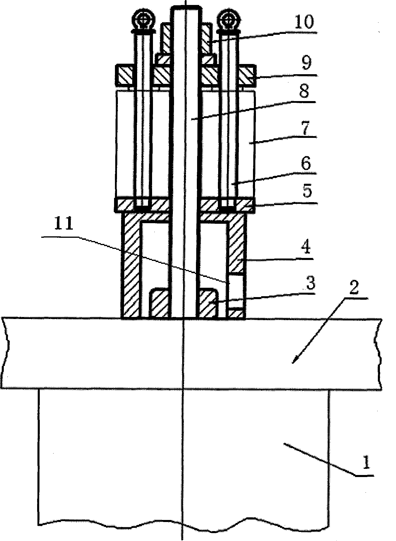
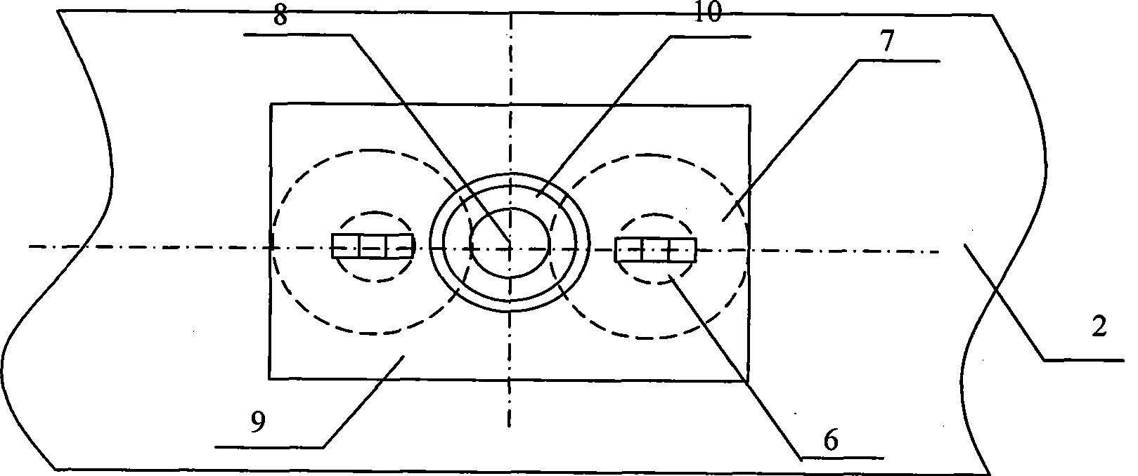
[0028] Such as figure 1 , figure 2 As shown, a symmetrical double-jack pressing device includes a pressure transmission device and a pressure application device. The pressure transmission device is a sleeve 4 with a closed upper end and a window hole 11 on the side for tightening the nut 3 . The sleeve 4 is in contact with the upper iron yoke through a screw 8 vertically fixed on the upper iron yoke 2 of the reactor, and a nut 3 is fastened at the joint between the upper iron yoke and the screw; the pressure applying device includes two upper and lower pressure plates 9, 5 , placed on the upper end surface of the sleeve 4 through the screw rod 8, two guide columns 6 are arranged between the upper and lower pressure plates, and the guide columns are symmetrically arranged relative to the screw rod 8; a small-tonnage hollow jack 7 is arranged on each guide column, and the upper pressure plate 9 The jack is fastened by a transition nut 10 .

Embodiment 2

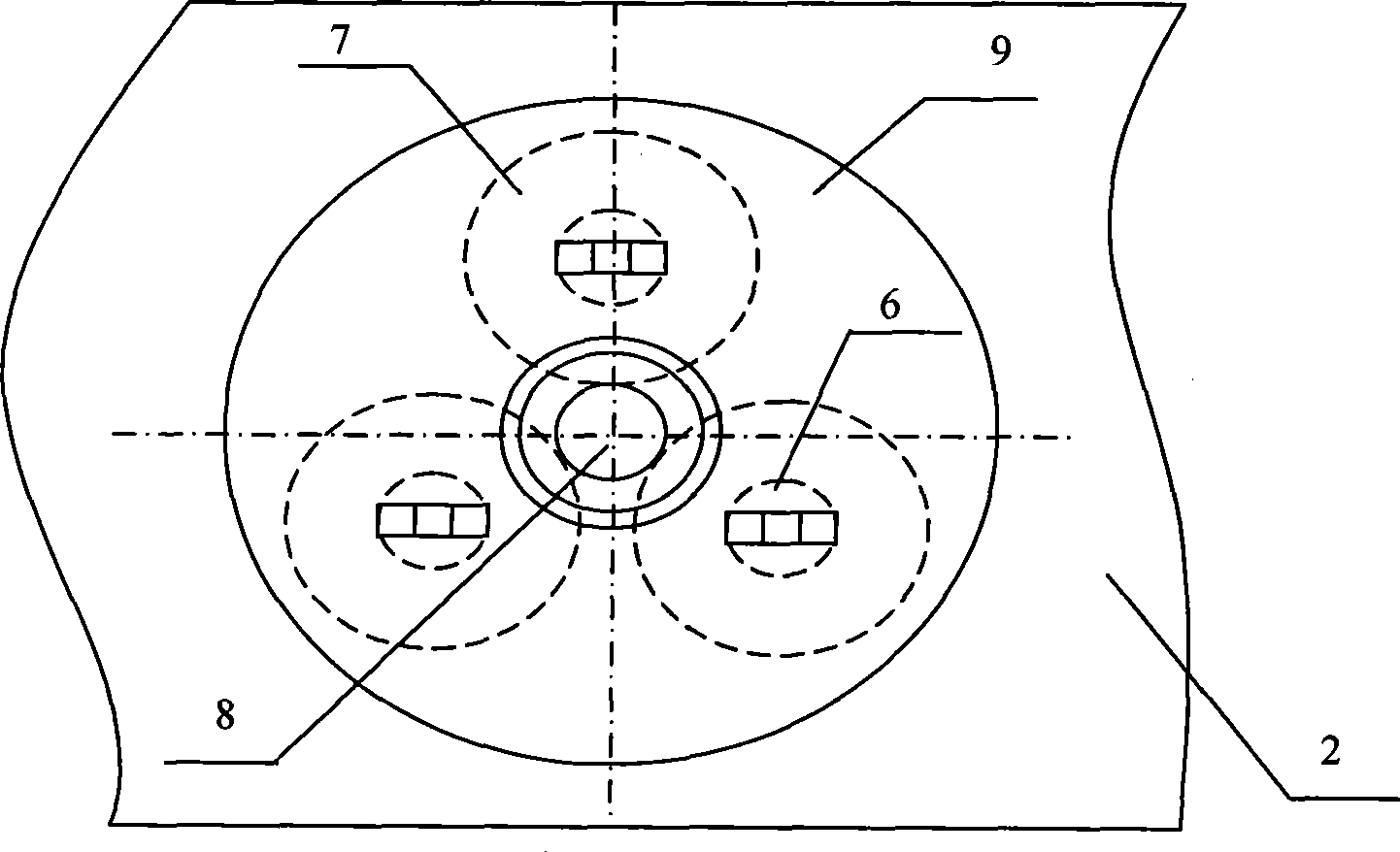
[0030] Such as image 3 As shown, in another three-jack pressing device, three guide columns are arranged and evenly arranged along the outer circumference of the screw rod 8, and three small-tonnage hollow jacks can be arranged correspondingly. All the other structures are the same as in Embodiment 1.

[0031] The pressing device of the present invention is not limited to the above two embodiments. According to the specifications of the reactor and the tonnage of the required jack and the tonnage of the existing small jack, the number of small jacks can be flexibly combined, such as from image 3 Based on the embodiment, the number of jacks can be 4, 6, 8 and other combinations. figure 1 The number of screw rods 8 fixed on the lower iron yoke 2 can be 1 to 15.


PUM


Abstract

The invention discloses compaction technology and a compaction device for an iron core of an electric reactor. Firstly, a screw which is fixed on a lower yoke and passes through a coil and an upper yoke is firmly screwed by a nut; a pressure transfer device passes through the screw until the pressure transfer device contacts the upper yoke; a lower platen is arranged on the pressure transfer device through the screw, and is at least provided with two guide posts, and the guide posts are symmetrically arranged relative to the screw or are evenly arranged along the periphery of the screw; each guide post is provided with a small tonnage hollow jack, and the jack is fastened by an upper platen through a transition nut; a hydraulic system of each jack is simultaneously supplied with oil, the jack acts downward, and the nut is firmly screwed when a clearance appears between the nut and the upper yoke; and finally the whole compaction work is finished after the transition nuts, the upper platen, the jacks, the lower platen and the pressure transfer device are orderly removed. The compaction technology and the compaction device flexibly combine the quantity of small jacks according to the needed jack tonnage and the tonnage of the prior small jacks, and have the characteristics of simple structure, low processing cost, and convenient use.

Description

technical field [0001] The invention relates to a reactor iron core pressing process and a pressing device. Background technique [0002] During the compression process of the reactor iron core, in order to control the height of the iron core, it is necessary to use a hollow jack to press the iron yoke on the iron core to tighten the coil after the coil is assembled. Due to the different specifications of the reactor, the pressure applied when tightening the coil is different, so the tonnage of the hollow jack used for tightening the coil is also different. A jack of less than 100 tons is most commonly used to compress the coil, and for a large reactor, a pressure of more than 100 tons will be required, and the tonnage of the equipped jack should be more than 100 tons. However, there are very few manufacturers producing large-tonnage jacks of more than 100 tons on the market. Even if there are, there are no off-the-shelf products. After buying, they may be idle for a long t...

Claims


Application Information

Patent Timeline
IPC IPC(8): H01F27/26H01F41/02
Inventor 翟海清田子九
Owner CHINA XD ELECTRIC CO LTD
Learn More