Method and device for safely drawing cash
A technology of safety and driving device, applied in the field of safe withdrawal, which can solve the problems of automatic teller machine error, disconnection, etc.
- Summary
- Abstract
- Description
- Claims
- Application Information
AI Technical Summary
Problems solved by technology
Method used
Image
Examples
example 1
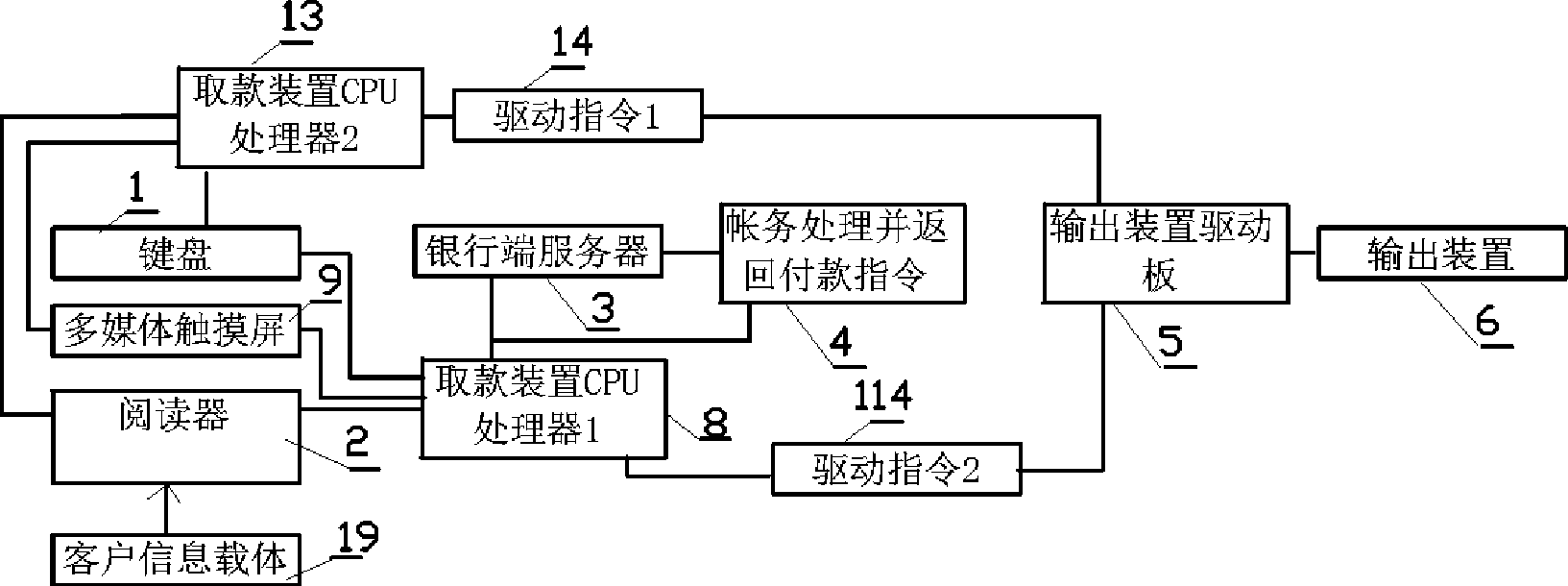
[0035] Example 1: see figure 1 It consists of 1 keyboard, 2 readers, 9 multimedia displays, 3 bank terminal accounting servers, 8 withdrawal device CPU processor 1, 5 output device driver board, 6 output devices; 2 withdrawal device CPU processor 2. 1, 2, 9, 3, 8, 114, 5 are the connection diagrams of the control part of the bank terminal account server; 1, 2, 9, 13, 14, 5 are the connection diagrams of the control part of the withdrawal device; 1, 3 and 9 are customer operating devices; 19 is customer information carrier, such as cards, passbooks, etc.
[0036] The CPU processor can be a computer or PLC programmable controller; the driver board can be an I / O card; the output device can be various payment devices, such as intelligent batch payment devices; it can also be a printer.
[0037] Its working process is: when the customer operates on the operating device, the control part of the bank-side account server and the control part of the withdrawal device are controlled at...
example 2
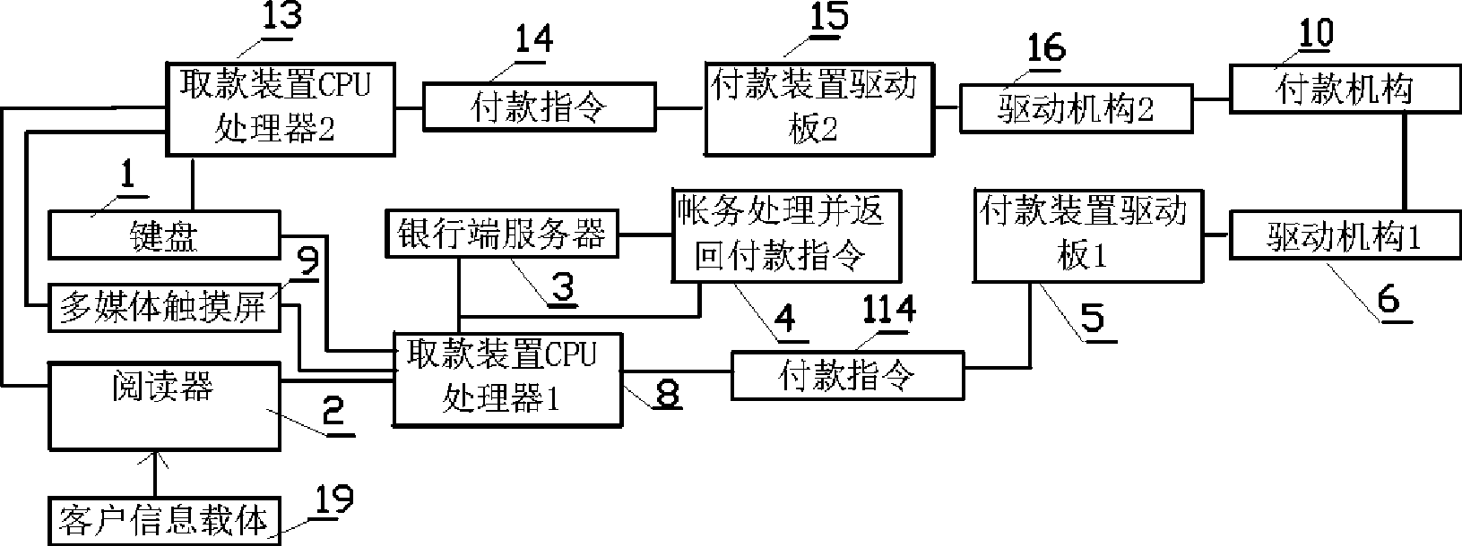
[0038] Example 2: see figure 2 , The control part of the bank account server has increased 6 driving mechanisms and 10 payment mechanisms; the control part of the withdrawal device has increased 16 driving mechanisms; the driving mechanism can also be a lock mechanism; others are the same as in Example 1.
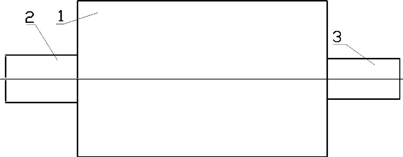
[0039] image 3 Shown in, 1 is a payment device, 2, 3 is a driving mechanism, and the driving mechanism can be installed on both sides or one side of the payment device, and the payment device is a cash storage and banknote dispensing device, such as an intelligent storage unit set; available in the market buy it online.
[0040] Figure 4 is a lock mechanism, 1 is a drive shaft, and 2 is an electromagnet; Figure 5 Middle 2 is the lockhole on the shaft, and 3 is the dead bolt. Its working process is that under normal conditions, the dead bolt is pressed against the lock hole under the action of the spring, and when the power is turned on, the electromagnet pulls the d...
PUM
 Abstract
Description
Claims
Application Information
 - R&D
- Intellectual Property
- Life Sciences
- Materials
- Tech Scout
- Unparalleled Data Quality
- Higher Quality Content
- 60% Fewer Hallucinations
Browse by: Latest US Patents, China's latest patents, Technical Efficacy Thesaurus, Application Domain, Technology Topic, Popular Technical Reports.
© 2025 PatSnap. All rights reserved.Legal|Privacy policy|Modern Slavery Act Transparency Statement|Sitemap|About US| Contact US: help@patsnap.com


