Composite lens
一种复合透镜、透镜的技术,应用在透镜、光学、仪器等方向,能够解决未充分填充树脂、不能树脂标记使用等问题,达到对位容易、精密生产率的效果
- Summary
- Abstract
- Description
- Claims
- Application Information
AI Technical Summary
Problems solved by technology
Method used
Image
Examples
no. 1 Embodiment approach
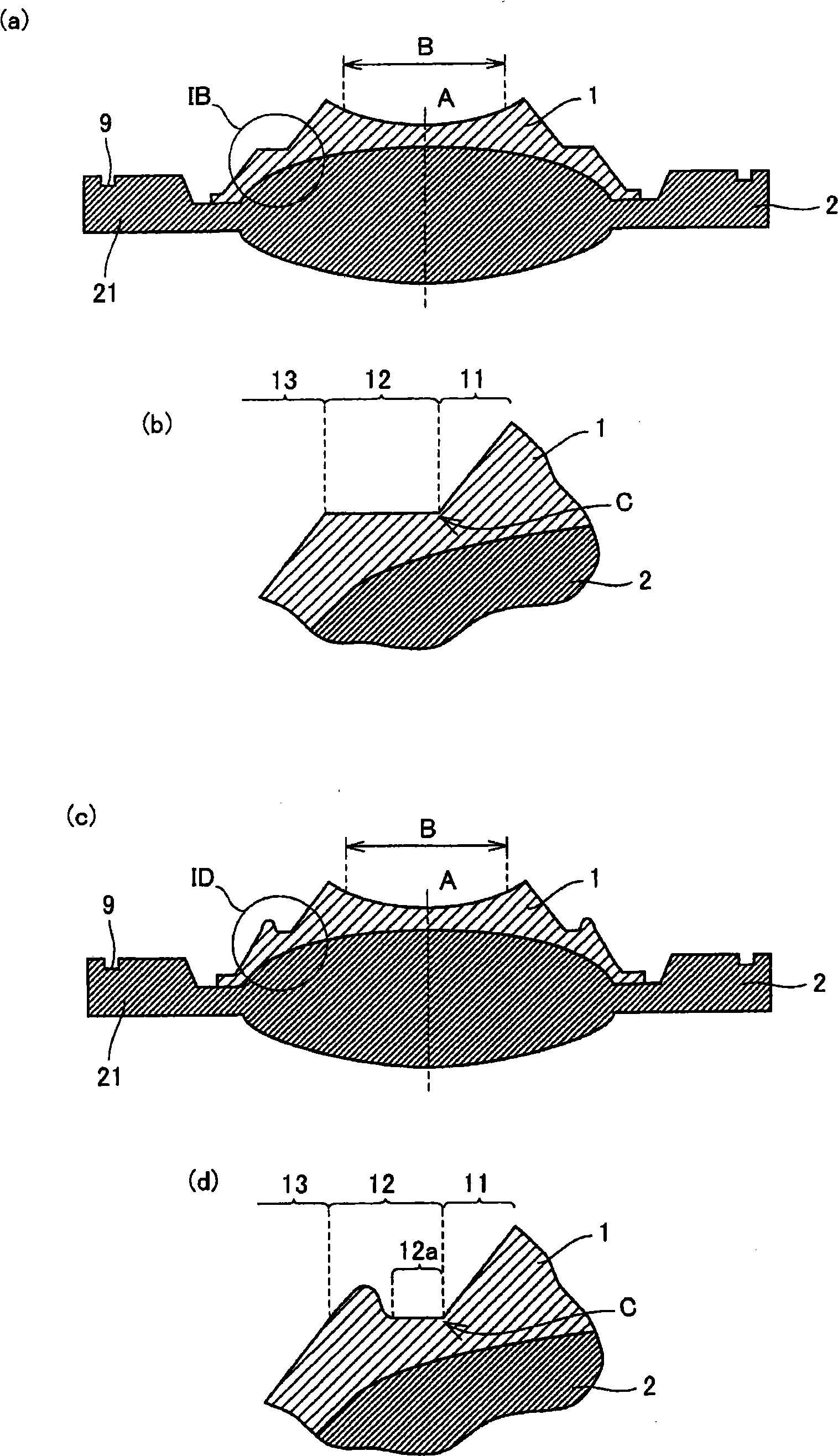
[0033] figure 1 (a) and figure 1 (b) shows a cross-sectional view of the compound lens in this embodiment. figure 1 (b) is figure 1 Enlarged view of part IB in (a). Such as figure 1 As shown in (a), the compound lens includes: a base lens 2 and a resin lens 1 on the base lens 2 . Such as figure 1 As shown in (b), the resin lens 1 has a first surface 11, a second surface 12 adjacent to the first surface 11, and a second surface adjacent to the second surface in order from the optical axis A toward the outer periphery in the region outside the optical effective diameter B. 12 adjacent to the third surface 13 . The first surface 11 has an inclined surface that becomes higher toward the optical axis A from the outer periphery, and the inclined surface is connected to the second surface. In addition, the second surface 12 is a surface substantially perpendicular to the optical axis A, and such a vertical surface is connected to the first surface. On the other hand, th...
no. 2 Embodiment approach
[0044] figure 1 (c) and figure 1 (d) shows the cross-sectional view of the compound lens in this embodiment. figure 1 (d) is figure 1 Enlarged view of part ID in (c). Such as figure 1 As shown in (c), the composite lens includes: a base lens 2 and a resin lens 1 on the base lens 2 . Such as figure 1 As shown in (d), in the region outside the optical effective diameter B, the resin lens 1 has, in order from the optical axis A toward the outer periphery: a first surface 11, a second surface 12 adjacent to the first surface 11, and a second surface 12 adjacent to the second surface. 12 adjacent to the third surface 13 . The first surface 11 has an inclined surface that becomes higher toward the optical axis A from the outer periphery, and this inclined surface is connected to the second surface. Furthermore, the second surface 12 has a surface 12 a substantially perpendicular to the optical axis A, and the surface 12 a is connected to the first surface 11 . On the o...
no. 3 Embodiment approach
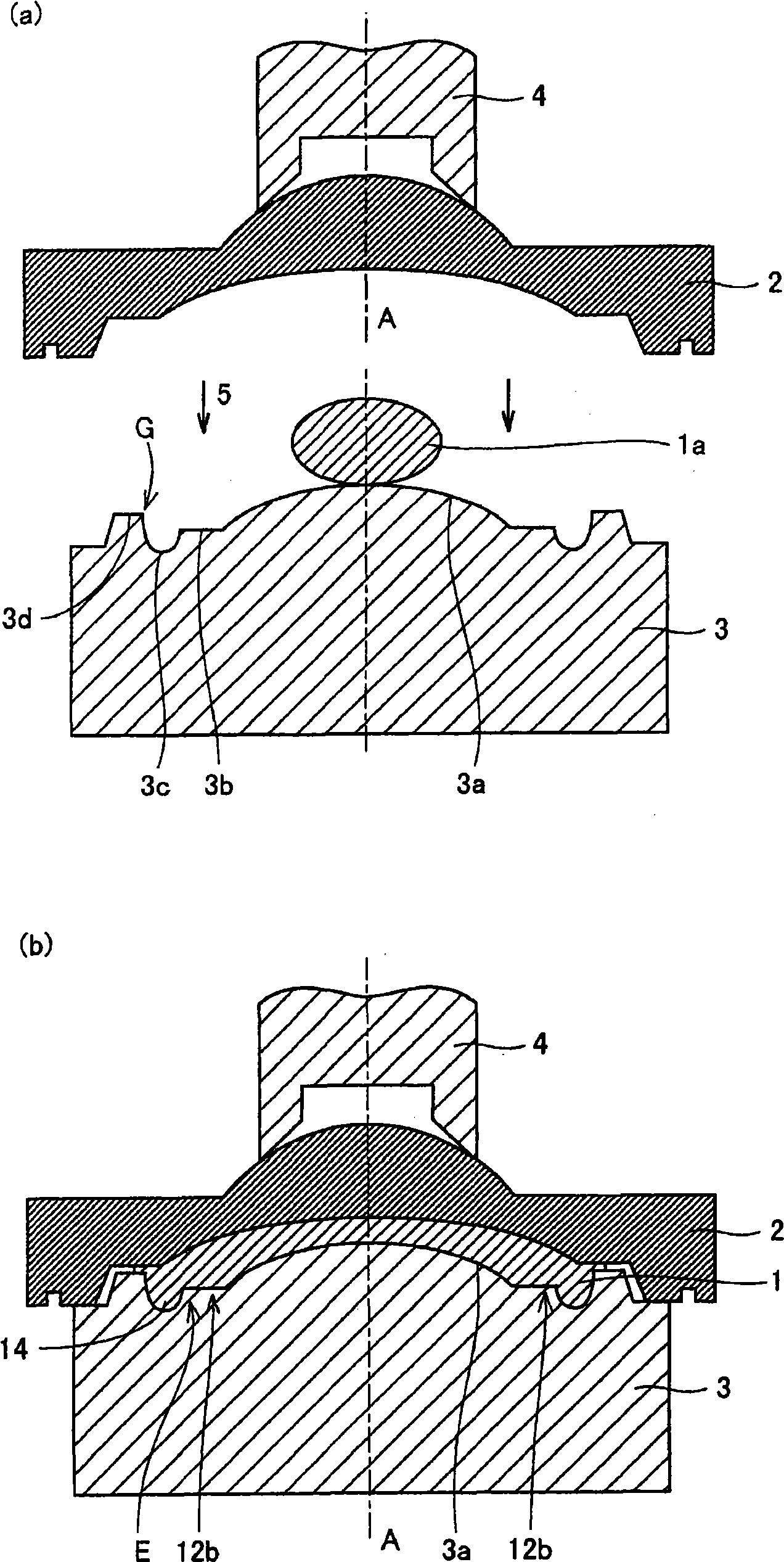
[0047] Image 6 (a) and Image 6 (b) shows a cross-sectional view of the compound lens in this embodiment. Image 6 (b) is Image 6 Enlarged view of VIB in (a). Such as Image 6 As shown in (a), the compound lens includes: a base lens 2 and a resin lens 1 on the base lens 2 . Such as Image 6 As shown in (b), the resin lens 1 has, in a region outside the optical effective diameter B, a surface 12b substantially perpendicular to the optical axis A, and a flange 14 protruding in the direction of the optical axis A connected to the outer periphery of the surface 12b. The connection portion E between the surface 12b and the flange 14 has a radius of curvature of 0.03 mm or less. Thus, the junction E of the face 12b and the flange 14 forms a sharp edge. In addition, a base material mark 9 that is an annular concave portion or an annular convex portion is provided on an outer edge (corner) portion 21 of the base lens 2 . In addition, since the manufactured compound lens also...
PUM
 Abstract
Description
Claims
Application Information
 - R&D Engineer
- R&D Manager
- IP Professional
- Industry Leading Data Capabilities
- Powerful AI technology
- Patent DNA Extraction
Browse by: Latest US Patents, China's latest patents, Technical Efficacy Thesaurus, Application Domain, Technology Topic, Popular Technical Reports.
© 2024 PatSnap. All rights reserved.Legal|Privacy policy|Modern Slavery Act Transparency Statement|Sitemap|About US| Contact US: help@patsnap.com


