Handheld rapid fixture

A handheld and fast technology, applied in the direction of clamps, manufacturing tools, etc., can solve the problems of poor positioning effect, difficult pressing and use of clamps, insufficient clamping or expansion force, etc., to achieve the effect of good tension

Inactive Publication Date: 2012-04-18
SHENG PU PROMOTION
View PDF0 Cites 1 Cited by
  • Summary
  • Abstract
  • Description
  • Claims
  • Application Information

AI Technical Summary

Problems solved by technology

[0002] The known hand-held quick clamps specially used for clamping or expanding the work object include: rod body, fixed clamp body, movable clamp body, first and second action parts, first and second elastic parts, buttons, driving handle and other components , the known clamp is more laborious when pressed, and in the clamped or expanded state, its fixing effect is not very stable
The reason is that the driving handle is used to push the action piece with a short force arm during the action, so it takes a lot of effort to press and start when using it, and the first and second action pieces are at ninety degrees to the rod body. Sleeve positioning, so the positioning effect when clamping or expanding is poor, and the force of clamping or expanding is insufficient

Method used


Image

  • Handheld rapid fixture
  • Handheld rapid fixture
  • Handheld rapid fixture

Examples


Embodiment Construction

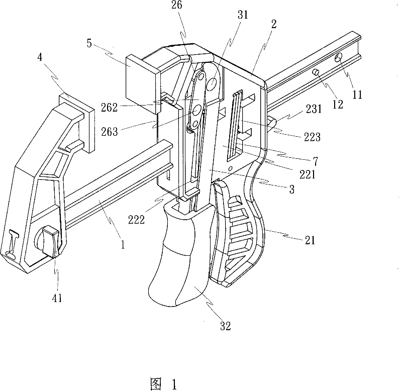
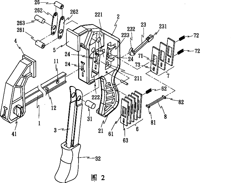
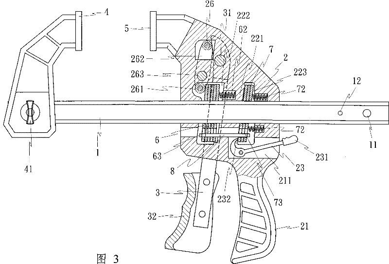
[0018] Such as Figure 1 to Figure 3 As shown, the hand-held quick clamp in the present invention includes: a moving rod 1, a fixed handle 2, a driving handle 3, a first clamping block 4 and a second clamping block 5 and other components, and the moving rod 1 runs through the fixed handle 2, a A set of action pieces 6 and a set of stop pieces 7, wherein:

[0019] Moving rod 1 is a strip rod body, which can be selected as Figure 1 to Figure 3 The shown I-shaped rod body or any rod body with better strength is provided with locking holes 11 and protruding stoppers 12 at both ends of the rod body, so that one end of the first clamping block 4 can be used to lock one end of the rod body. Combine;

[0020] The fixed handle 2, the lower end is the grip part 21, the upper end utilizes the partition rib 221 to form a front accommodating chamber 222 and a rear accommodating chamber 223, and a second clamping block 5 is arranged above the fixed handle 2, and the grip part 21 is opene...


PUM


Abstract

The invention provides a handheld rapid fixture, which comprises a shifting lever, a fixed handle, a drive handle, a first grip block, a second grip block and other members. The shifting lever penetraThe invention provides a handheld rapid fixture, which comprises a shifting lever, a fixed handle, a drive handle, a first grip block, a second grip block and other members. The shifting lever penetrates through the fixed handle, a group of action plates and a group of stop plates. One end of the body of the shifting lever is provided with the first grip block through locking. The second grip bloctes through the fixed handle, a group of action plates and a group of stop plates. One end of the body of the shifting lever is provided with the first grip block through locking. The second grip block is arranged above the fixed handle which is pivotally connected with the drive handle. A movable apical axis is erected on the fixed handle and is provided with a beam barrel at another end. When thk is arranged above the fixed handle which is pivotally connected with the drive handle. A movable apical axis is erected on the fixed handle and is provided with a beam barrel at another end. When the drive handle is pressed, the top end of the body of the drive handle drives the apical axis, and furthermore, the action plate is pressed by the beam barrel. The dislocated shift of the action platee drive handle is pressed, the top end of the body of the drive handle drives the apical axis, and furthermore, the action plate is pressed by the beam barrel. The dislocated shift of the action plate is used for driving the shifting lever to generate unidirectional displacement, thus causing the two grip blocks to generate the operation function of gripping or expanding. The handheld rapid fixturis used for driving the shifting lever to generate unidirectional displacement, thus causing the two grip blocks to generate the operation function of gripping or expanding. The handheld rapid fixture saves more labor in operation and has better holding force and stretching tension.e saves more labor in operation and has better holding force and stretching tension.

Description

technical field [0001] The present invention relates to a clamp, more specifically, to a hand-held quick clamp specially used for clamping or expanding a work object. Background technique [0002] The known hand-held quick clamps specially used for clamping or expanding the work object include: rod body, fixed clamp body, movable clamp body, first and second action parts, first and second elastic parts, buttons, driving handle and other components , the known clamp is relatively laborious when pressed, and in the clamped or expanded state, its fixing effect is not very stable. The reason is that the driving handle is used to push the action piece with a short force arm during the action, so it takes a lot of effort to press and start when using it, and the first and second action pieces are at ninety degrees to the rod body. Sleeve positioning, so the positioning effect when clamping or expanding is poor, and the force of clamping or expanding is insufficient. Contents of...

Claims


Application Information

Patent Timeline
Patent Type & Authority Patents(China)
IPC IPC(8): B25B5/02B25B5/06B25B5/16
Inventor 郭子祺
Owner SHENG PU PROMOTION
Why Eureka
Try Eureka