


Quick Research
Generate reliable direction feasibility study reports for your R&D in just a few steps.

Technical Q&A
Discover and master advanced knowledge NOW. Basics, ideas, possibilities, all at once.

Find Solutions
As an expert in R&D theories, this can generate solutions to your technical problems instantly.

Evaluate Feasibility
Analyze your overall solution with one click, know your potential R&D risks in advance.

Monitor Landscape
Get weekly tech updates, stay abreast of the latest tech innovations and key insights.
Installation method of sensor free from pressure release
An installation method and sensor technology, applied in the field of sensors, can solve problems affecting production, economic losses, etc., and achieve the effects of easy installation, high measurement accuracy, and safe use
- Summary
- Abstract
- Description
- Claims
- Application Information
AI Technical Summary
Problems solved by technology
Method used
Image

Examples
Embodiment 1
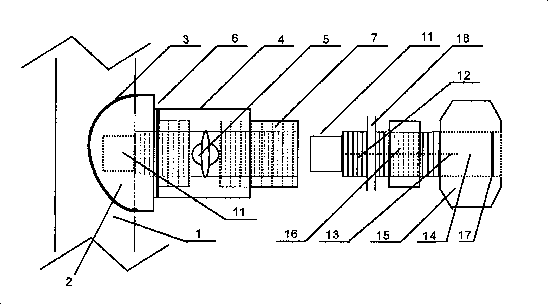
[0020] exist figure 1 and figure 2 In the three-dimensional schematic diagram of the installation method of the non-pressure relief sensor shown in the figure, the valve seat 2 is fixed on the pipeline 1 by welding on one side of the pipeline 1, and the welding seam at the contact part between the peripheral edge 3 of the bottom of the valve seat 2 and the pipeline 1 It is in a sealed state; the middle part of the valve seat 2 is through-type hollow, and the valve seat tube 4 protruding out of the valve seat 2 has internal and external spiral thread openings and is integrated with the valve seat 2, and there is a spiral thread opening in the tube; the valve seat 2 tube The outside is a spiral thick wire port; the outer spiral sleeve of the valve seat tube 4 is connected with the lower end tubular joint of the ball valve type valve 5, and the 6-type connection is sealed with a sealing tape. Corresponding to the pipe size; the upper end of the ball valve type valve 5 has a val...
Embodiment 2
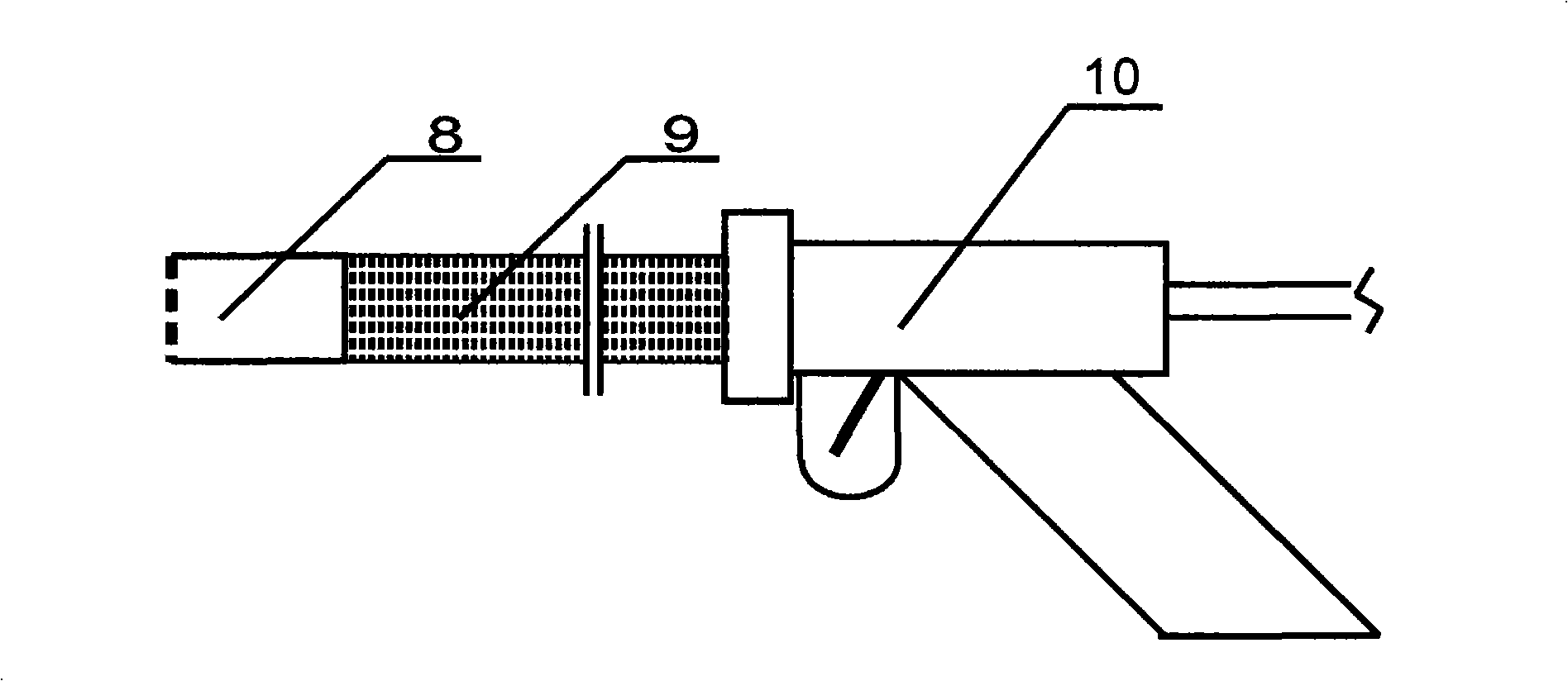
[0028] exist figure 1 and figure 2 In the three-dimensional schematic diagram of the installation method of the non-pressure relief sensor shown in the figure, other implementations are basically the same as Example 1, only two points are different from Example 1. One is that the connection between the valve seat 2 and the pipeline 1 is closed. The valve seat 2 is fixed on the pipeline, and the contact part between the bottom edge 3 of the valve seat 2 and the pipeline is sealed with a sealing pad; The bar can be stirred with both hands to make the hole opener 8 rotate on the pipe 1 wall to make a hole.
PUM
 Abstract
Description
Claims
Application Information
 - R&D Engineer
- R&D Manager
- IP Professional
- Industry Leading Data Capabilities
- Powerful AI technology
- Patent DNA Extraction
Browse by: Latest US Patents, China's latest patents, Technical Efficacy Thesaurus, Application Domain, Technology Topic, Popular Technical Reports.
© 2024 PatSnap. All rights reserved.Legal|Privacy policy|Modern Slavery Act Transparency Statement|Sitemap|About US| Contact US: help@patsnap.com