Communication device and apparatus, communication device control method and control program, and recording medium
A technology of a communication device and a control unit, which is applied to the application of power line communication, wireless communication, data exchange through path configuration, etc., and can solve problems such as not considering QoS and not installing a notification structure
- Summary
- Abstract
- Description
- Claims
- Application Information
AI Technical Summary
Problems solved by technology
Method used
Image
Examples
no. 1 Embodiment approach
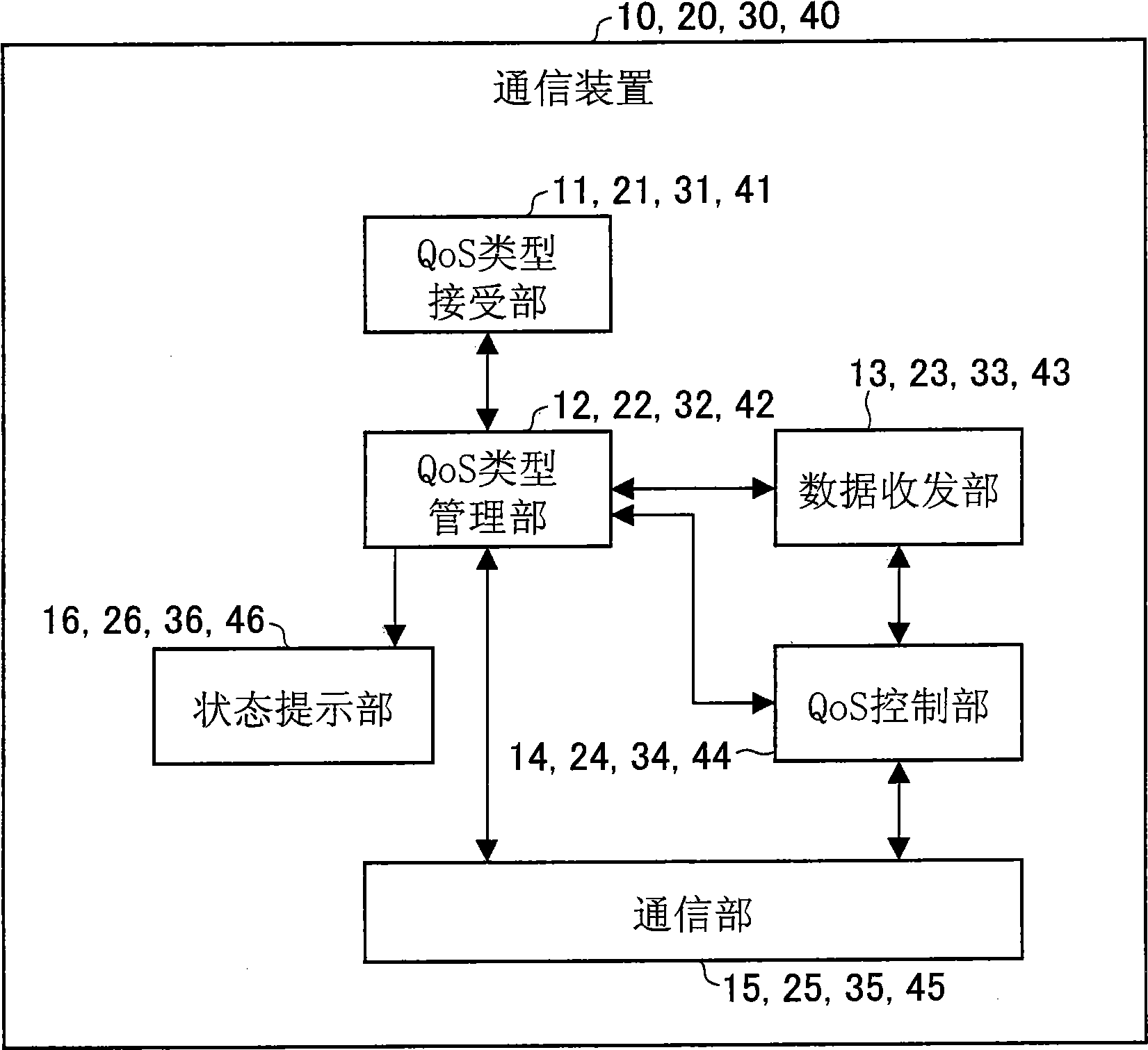
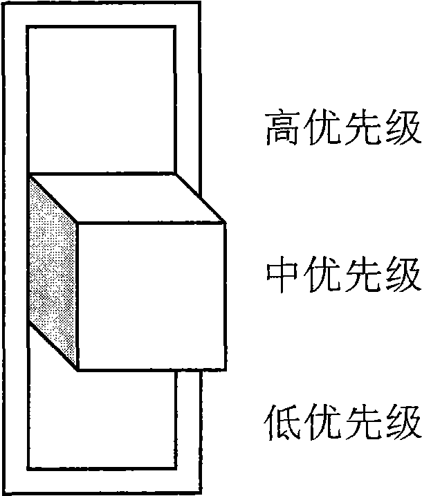
[0260] In the first embodiment, a method will be described in which, for a communication device on a content receiving side, a user designates a reception priority for each communication device on a content receiving side, uses the reception priority as a QoS type, and Based on this designation, the entire network performs QoS control through priority QoS. Figure 4 represents the entire processing flow.
[0261]
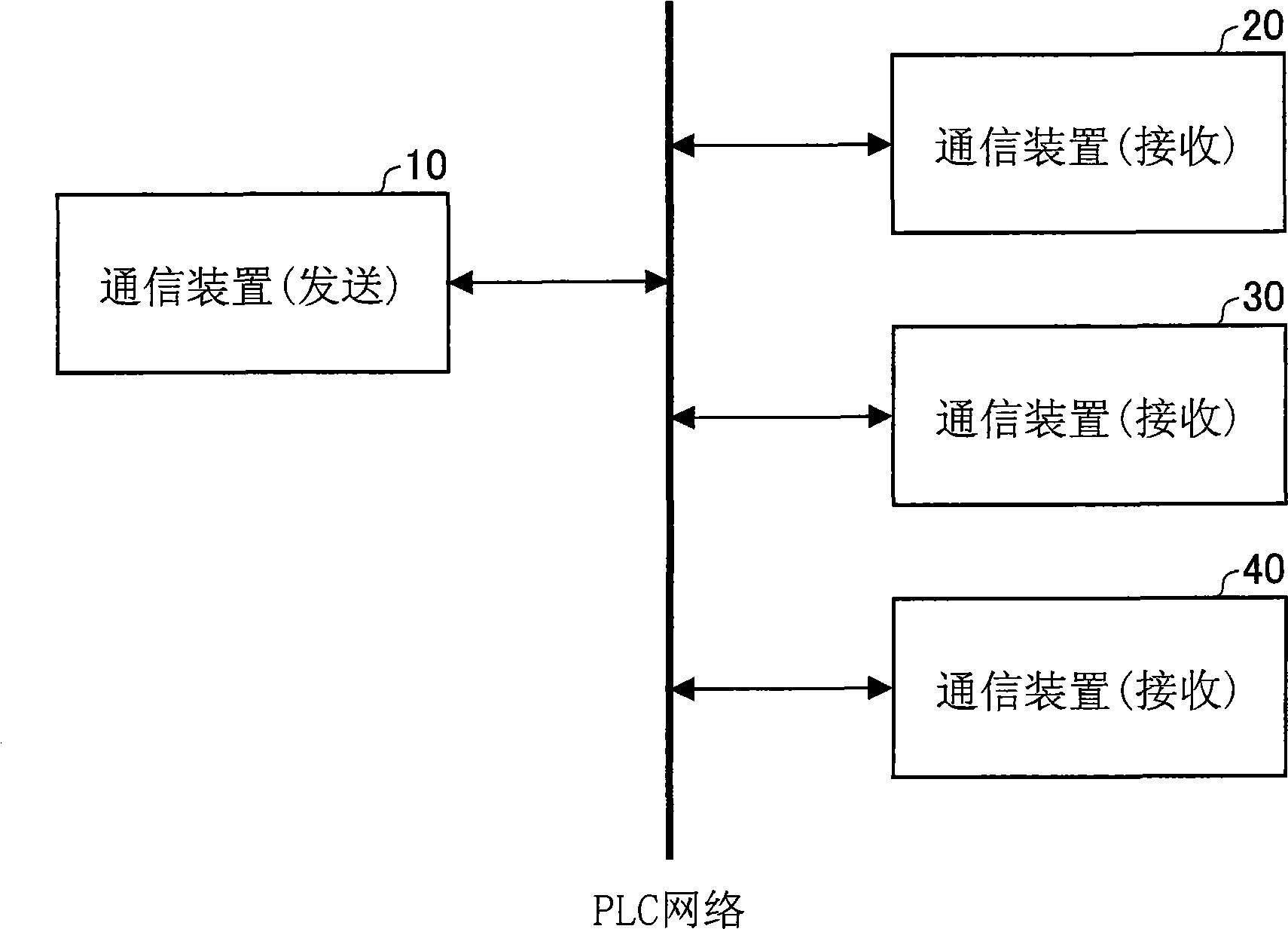
[0262] figure 2 It is a figure which shows the network structure in this embodiment. In this embodiment, data transmission is performed from the communication device 10 to the communication device 20 , data transmission is performed from the communication device 10 to the communication device 30 , and data transmission is performed from the communication device 10 to the communication device 40 . Each communication device has a built-in function for transmitting data to other communication devices via a network. The network may be a wired LAN such as Ethernet,...
no. 2 Embodiment approach
[0405] In the second embodiment, a method will be described in which, for the PLC adapter on the content receiving side, the user designates the type of content received by each PLC adapter as the QoS type, and based on this designation, the entire network performs parametric QoS QoS control. Figure 9 Indicates the entire processing flow.
[0406]
[0407] Image 6 It is a figure which shows the network structure in this embodiment. This embodiment differs from the first embodiment in that the PLC adapter connected to the PLC network for communication is not the same device as the device that actually transmits and receives content data.
[0408] In this embodiment, parametric QoS is used. Regarding the parametric QoS, it is necessary to set up a master station (master station) in the network, and the master station manages the QoS of the entire network. The PLC adapter 50 in this embodiment has the function of the master station, but it is not limited to this, and othe...
no. 3 Embodiment approach
[0623] In the third embodiment, a flow is described in which, for the PLC adapter of the content receiver, the user specifies the type of content to be received by each adapter as a QoS type, and the entire network implements parametric QoS according to the QoS type QoS control. Figure 13 Indicates the entire processing flow.
[0624]
[0625] Figure 12 Shows the network configuration of this embodiment. Its difference is: relative to the sending station 60 of content data and the receiving station 70,80 of content data, there is the master station 50 of parametric QoS in addition; hard disk recorder 170.
[0626] The basic flow of QoS control is almost the same as that of the second embodiment, but in the second embodiment, the QoS setting request packet is transmitted from the PLC adapter 60 on the content receiving side. In contrast, the biggest difference in this embodiment is that the QoS setting request packet is sent through the PLC adapter 60 of the content sen...
PUM
 Abstract
Description
Claims
Application Information
 - Generate Ideas
- Intellectual Property
- Life Sciences
- Materials
- Tech Scout
- Unparalleled Data Quality
- Higher Quality Content
- 60% Fewer Hallucinations
Browse by: Latest US Patents, China's latest patents, Technical Efficacy Thesaurus, Application Domain, Technology Topic, Popular Technical Reports.
© 2025 PatSnap. All rights reserved.Legal|Privacy policy|Modern Slavery Act Transparency Statement|Sitemap|About US| Contact US: help@patsnap.com


