Spouted pouch

A technology with a spout and a spout, which is applied to the field of bags with a spout, can solve the problems of automatic closure and other problems that have not been proposed, and achieve the effect of preventing rupture and slipping.

Inactive Publication Date: 2009-08-19
TOYO SEIKAN KAISHA LTD +1
View PDF0 Cites 1 Cited by
  • Summary
  • Abstract
  • Description
  • Claims
  • Application Information

AI Technical Summary

Problems solved by technology

[0009] However, in the structure disclosed in the above Patent Publication 1, the spout needs to be made to have a specific shape, and it is difficult to apply this spout to the existing pouch with a spout.
In addition, no technology is proposed to solve the problem of automatic closure

Method used


Image

  • Spouted pouch
  • Spouted pouch
  • Spouted pouch

Examples


no. 1 example

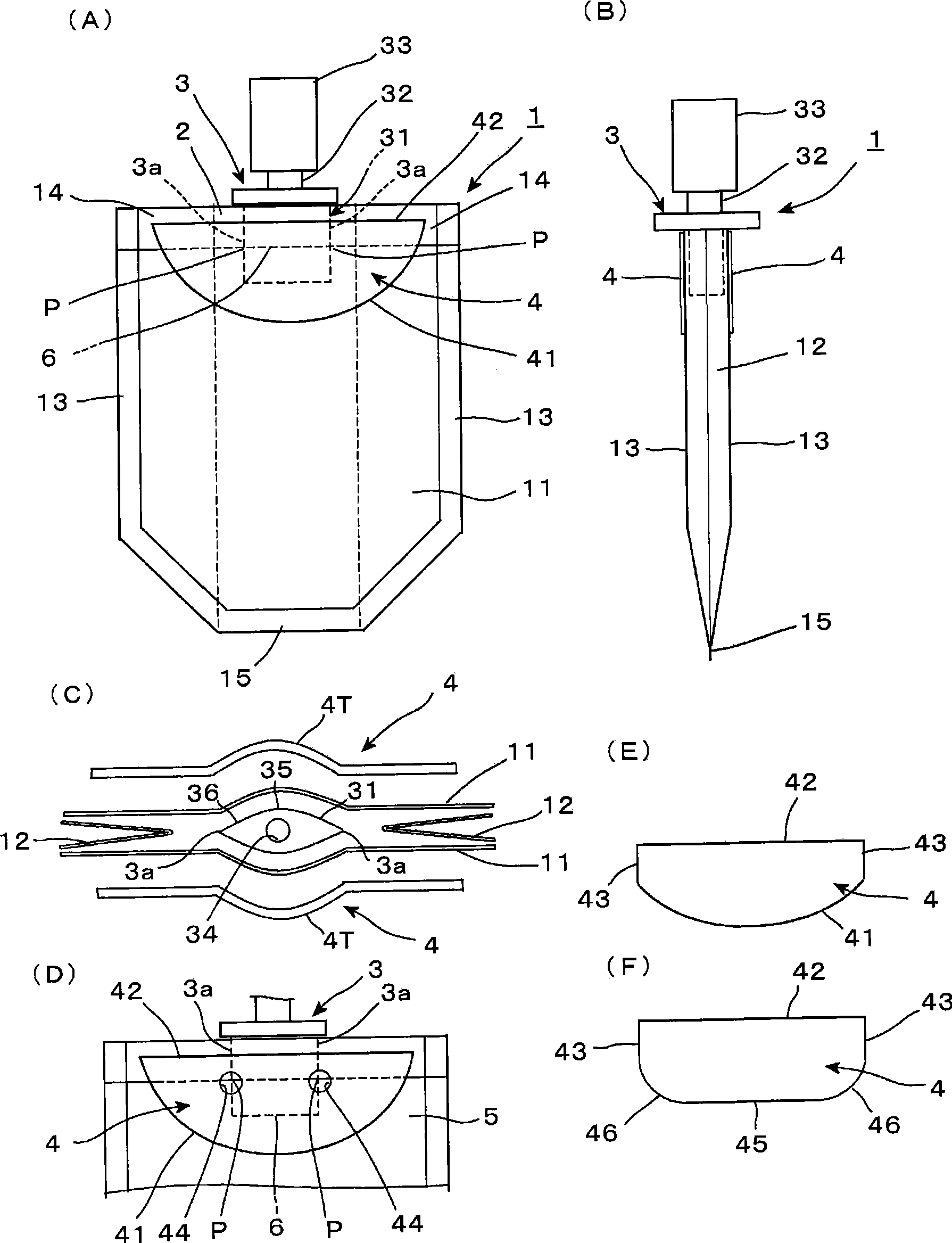
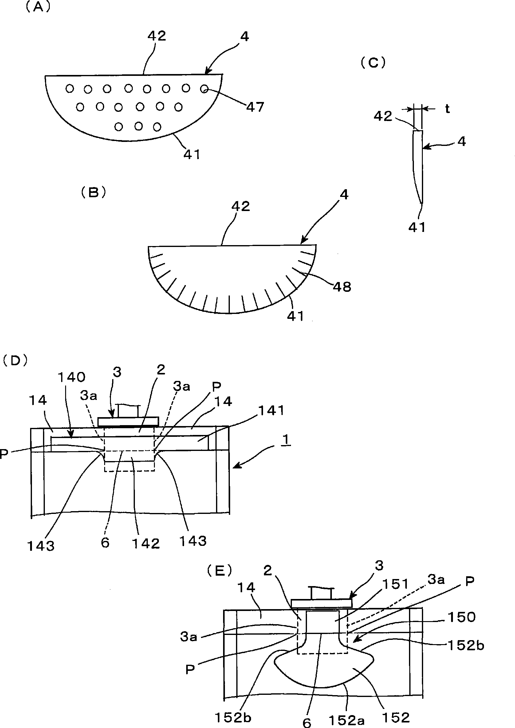
[0063] figure 1 A spouted bag according to a first embodiment of the invention is shown.

[0064] The bag with a spout has a bag shape made by laminating flexible films, and includes: a bag body 1 in which end portions of the films forming a seam are thermally fused and sealed; and a spout 3 provided on The film end portions of the bag body 1 are thermally fused between and together with these film end portions. Further, the stress dispersing sheet 4 is provided as a stress dispersing member and bonded to the outer surface of the bag body 1 so as to partially cover the spout sealing portion 2 and the deformable film portion 5 of the spout 3 in the following manner: The stress dispersing sheet 4 is made to straddle the boundary portion 6 between the spout sealing portion 2 as the thermal fusion portion and the deformable film portion 5 facing the inner space of the bag body 1 .

[0065] The bag body 1 in the example shown is of the newspaper bag (gazette bag) type, and as ...

no. 2 example

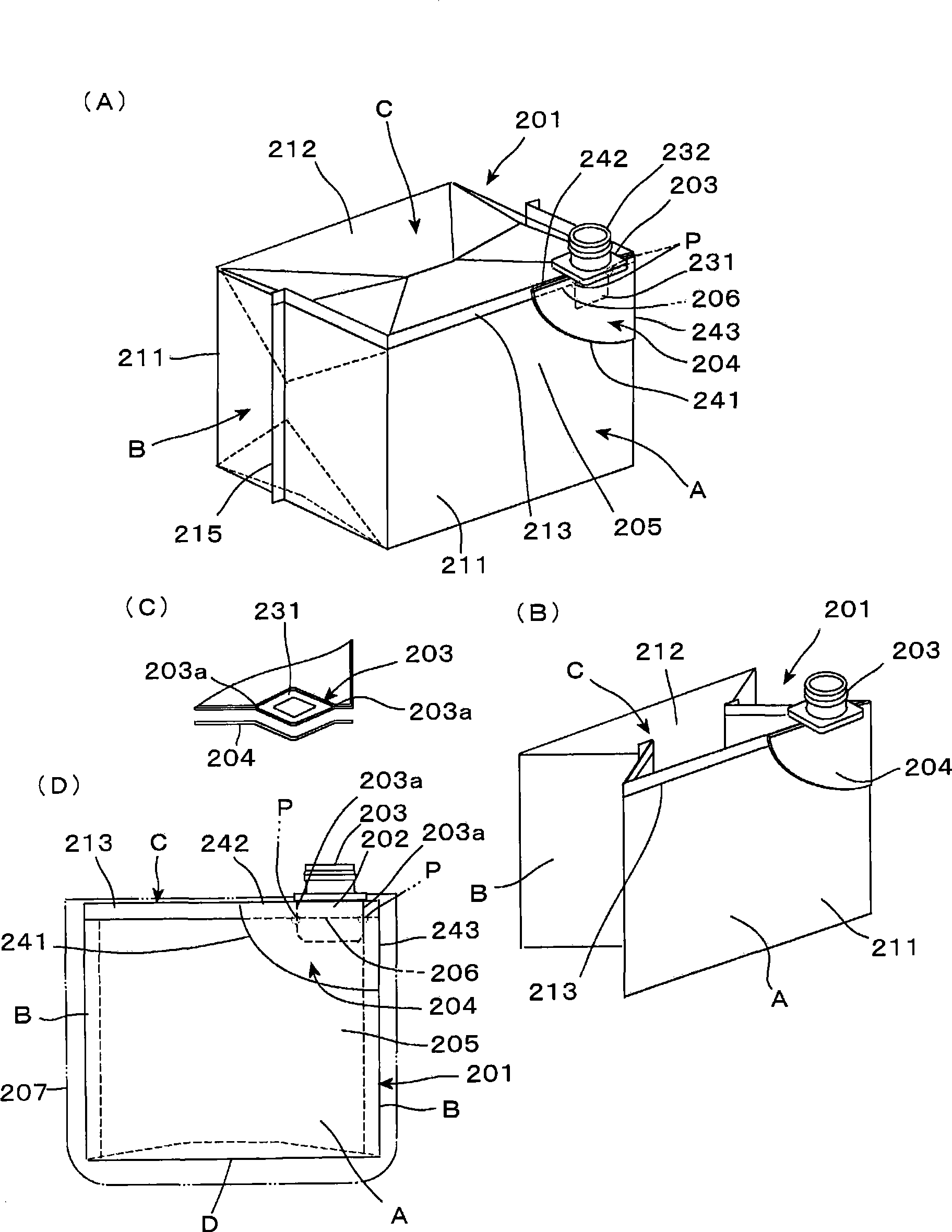
[0093] image 3 A spouted bag according to a second embodiment of the invention is shown.

[0094] The spouted bag is accommodated in a packaging container having high rigidity and is fixed to the packaging container 207 via the spout 203 . In this structure, the capacity of the bag in the state of being accommodated in the packaging container 207 is reduced.

[0095] The bag with a spout has a bag body constituted by laminating flexible films, and the bag body is provided with a bag body 201 and a spout 203, wherein the bag body 201 is formed by thermally fusing the ends of the films and then sealing them to form a connection The spout 203 is inserted between the film end portions of the bag body 201 and is thermally fused and sealed together with the film end portions.

[0096] The pouch body 201 is manufactured by bending a flat film material into a pair of front and rear flat surface film portions 211, 211 and a pair of side surface film portions 212, 212 folded between ...


PUM

PropertyMeasurementUnit
thicknessaaaaaaaaaa

Abstract

To provide a spouted pouch that is simple in structure, being capable of dispersing any stress concentrated on a boundary area of spout seal portion, to thereby attain enhancements of pressure resistance and drop impact resistance. The spouted pouch is one having pouch main body (1) consisting of a bag formed by lamination of flexible films wherein the interspace between film edge portions as a seam is sealed by hot melt adhesion and having spout (3) fitted in the interspace between film edge portions of the pouch main body (1), the spout (3) sealed by hot melt adhesion together with the film edge portions, characterized in that on the external surface of the pouch main body (1), astride boundary area (6) between spout seal portion (2) and transformable film portion (5) facing the internal space of the pouch main body (1), there is provided stress dispersion piece (4) attached so as to partially cover both the spout seal portion (2) and the transformable film portion (5).

Description

technical field [0001] The invention relates to a pouch with a spout on the pouch body. Background technique [0002] The spout bag of this conventional structure is manufactured by thermally fusing a spout having high hardness with a bag body made of a flexible film. [0003] Figure 4 A conventional plain spouted bag is shown. That is, such a bag with a spout is a bag body formed by laminating a plurality of flexible films, and the bag includes a bag body 101 and a bag spout 103 by heat fusing and then sealing the film end portion of the bag body to Made by forming a seam, the spout is inserted between film end portions of the bag body 101, and then heat-fused and sealed together with the film end portions. [0004] However, there is a difference in hardness between the deformable film portion 104 facing the inner accommodation space of the bag body 101 and the spout 103 which is a molded product. Therefore, when the pressure of the articles stored in the bag increases ...

Claims


Application Information

Patent Timeline
Patent Type & Authority Applications(China)
IPC IPC(8): B65D33/02B65D33/38
CPCB65D75/5883B65D33/02B65D33/00
Inventor 相川孝之藤田紫川村公一
Owner TOYO SEIKAN KAISHA LTD
Why Eureka
Try Eureka