Apparatus for transmission and recovery of aerodynamic profile element, and aerodynamic profile element

A technology of aerodynamics and surface elements, applied in wind propulsion elements, transportation and packaging, emission reduction based on propulsion, etc., can solve the problem of difficult control of surface elements, weak strength and direction of wind conditions, flight attitude of surface elements Difficulties and other problems, to achieve the effect of easy manipulation

Inactive Publication Date: 2013-01-02
SKYSAILS GMBH & CO
View PDF2 Cites 0 Cited by
  • Summary
  • Abstract
  • Description
  • Claims
  • Application Information

AI Technical Summary

Problems solved by technology

[0015] A first problem here is that the prevailing wind conditions close to the ground make it difficult to create a stable flight attitude of the profiled elements, since the wind conditions are often weak and are moreover variable with respect to intensity and direction
Therefore, the lower the surface element flies, the more difficult it is to control

Method used


Image

  • Apparatus for transmission and recovery of aerodynamic profile element, and aerodynamic profile element
  • Apparatus for transmission and recovery of aerodynamic profile element, and aerodynamic profile element
  • Apparatus for transmission and recovery of aerodynamic profile element, and aerodynamic profile element

Examples


Embodiment Construction

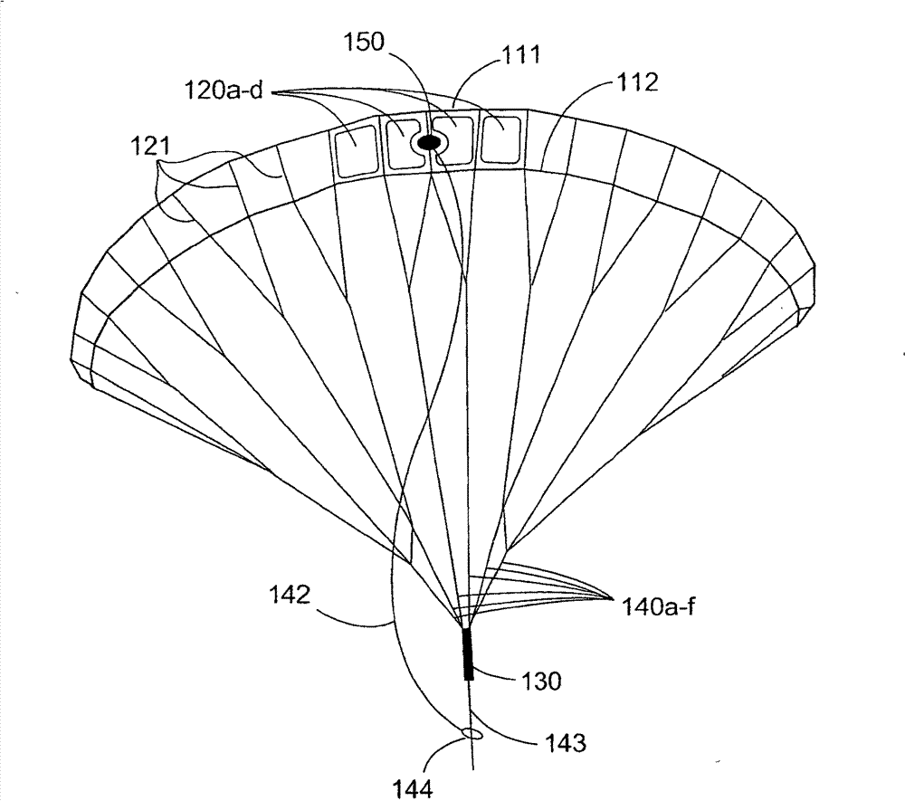
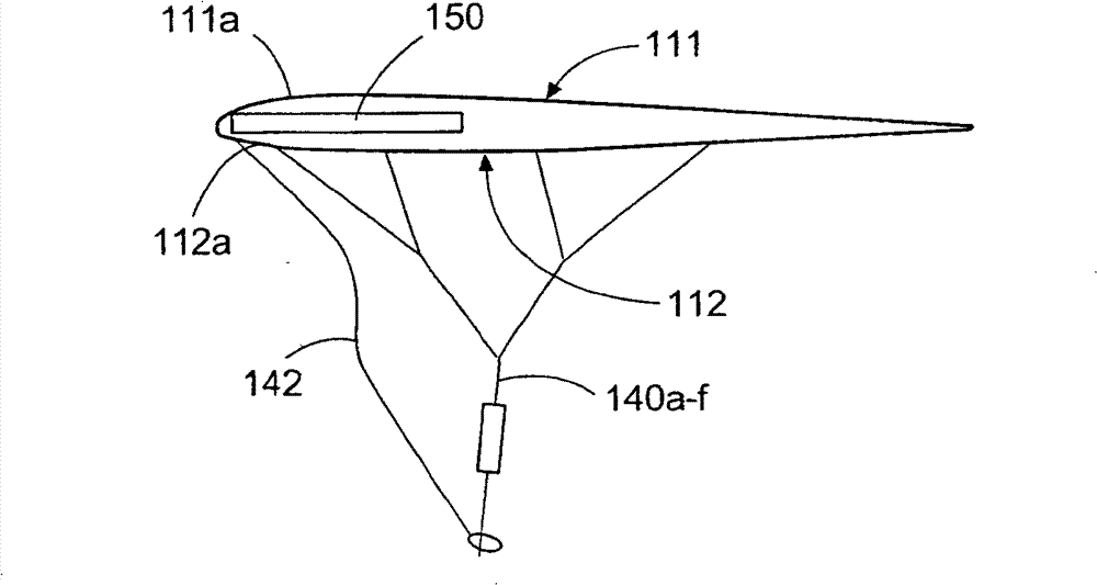
[0072] refer to figure 1 with figure 2 , the aerodynamic profile element in the form of the kite sail 100 according to the invention has a first upper layer 111 and a second lower layer 112 . in accordance with figure 1 Between the front edges 111a and 112a can clearly be seen a plurality of openings 120a-d in the front view of , which are used for the ventilation of the interior cavity between the upper layer 111 and the lower layer 112 . The openings are arranged around the horizontal longitudinal axis of the kite sail. There are no openings in the outer region between the leading edges 111a, 112a.

[0073] The upper and lower layers are connected to each other by means of a plurality of webs 121 . Such a connection consisting of an upper layer, a lower layer and a web is connected to the basket 130 by means of pulling ropes. In this case, a large number of pulling ropes are fastened to the kite, said pulling ropes are grouped together in the direction of the gondola t...


PUM


Abstract

The aerodynamic profile element has a flexible top layer (111) and a flexible bottom layer (112). The profile element is extended by a rod element which runs in a longitudinal direction of the profile element and is used for stabilizing the aerodynamic profile. A reefing line is deflected on the rod element from a reefing line section (260a,262a) that extends from a fastening point at an end in a transversal direction of the profile element of the top or bottom layer into a reefing line section extending in the longitudinal direction. An independent claim is also included for a starting and recovery device for a profile element.

Description

technical field [0001] The invention relates to an aerodynamic profile element for generating energy by means of traction, in particular for driving water vehicles, comprising: [0002] a flexible upper layer extending in the transverse and longitudinal directions; [0003] a flexible lower layer extending parallel to the upper layer and connected to the upper layer by means of a plurality of webs extending in the depth direction of the profile element; [0004] an air-filled inner cavity between the upper and lower layers; [0005] at least one vent for interior cavity ventilation arranged between two mutually parallel leading edges of the upper and lower tiers; [0006] a plurality of pull cords having first ends secured to the profile element at spaced locations and second ends connected to the pull cords for connecting the profile element to the water vehicle; [0007] A plurality of reef lines having their first ends fixed to the tier and / or the web, said reef lines be...

Claims


Application Information

Patent Timeline
Patent Type & Authority Patents(China)
IPC IPC(8): B63B35/79B63H9/06B64C31/06B63B15/00
CPCB64C31/06B63H9/1021B64C2031/065B63B35/7976B63B15/0083B63H9/0685B63H9/072B63B2035/009Y02T70/5236
Inventor 斯特凡·弗拉格斯特凡·布拉贝克
Owner SKYSAILS GMBH & CO
Why Eureka
Try Eureka