
Method and apparatus for correcting data error in image processing system

An image processing and data technology, applied in the field of data error correction, can solve the problems of accumulation and system crash, and achieve the effect of solving the crash problem at a low cost

Inactive Publication Date: 2009-08-19
WUXI ZGMICRO ELECTRONICS CO LTD
View PDF0 Cites 2 Cited by
  • Summary
  • Abstract
  • Description
  • Claims
  • Application Information

AI Technical Summary

Problems solved by technology

[0004] In the process of realizing the technical solution of the present invention, it is found that in the existing image processing system, when the amount of data of each line or frame is inconsistent with the preset amount of data, the system will crash, and errors will accumulate until Restart, and all modules involved in data transmission processing have such problems

Method used


Image

  • Method and apparatus for correcting data error in image processing system
  • Method and apparatus for correcting data error in image processing system
  • Method and apparatus for correcting data error in image processing system

Examples


Embodiment Construction

[0046] In order to make the purpose, technical solutions and advantages of the embodiments of the present invention more clear, specific embodiments will be described in detail below with reference to the accompanying drawings.

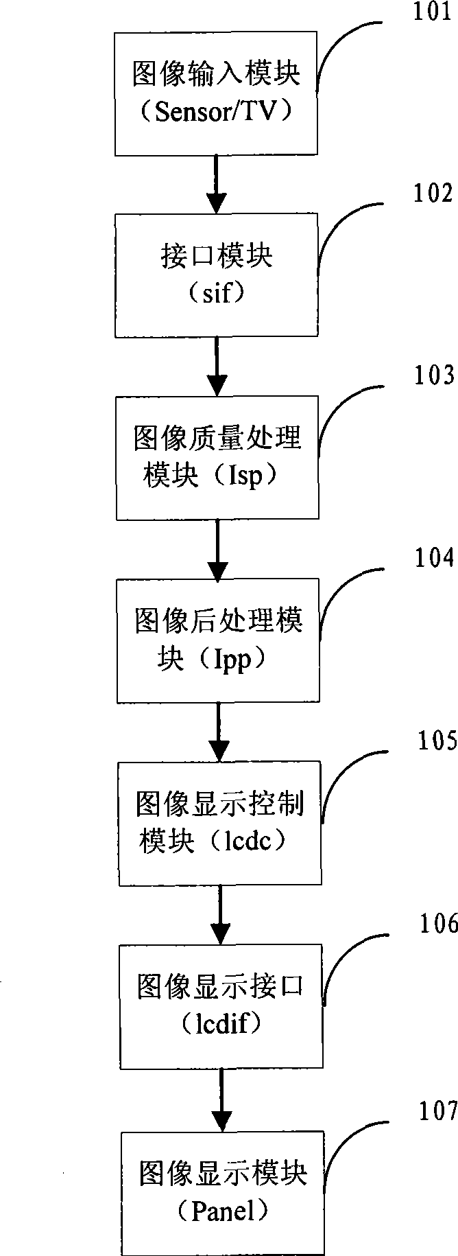
[0047] figure 1 is a schematic diagram of an existing image processing system, such as figure 1 As shown, the image processing system includes:

[0048] The image input module (Sensor / TV) 101 is used for: mainly inputting continuous images into the sif module in yuv format or other data formats; data is input in units of frames;

[0049] Interface module (sif) 102 is used for: as the interface of image input module 101 and concrete chip, plays connection image input module 101 and Isp module in this system;

[0050] The image quality processing module (Isp) 103 is configured to: process the image quality.

[0051] The image post-processing module (Ipp) 104 is used for: digging, shrinking, and enlarging the image...

[0052] The image display contr...


PUM


Abstract

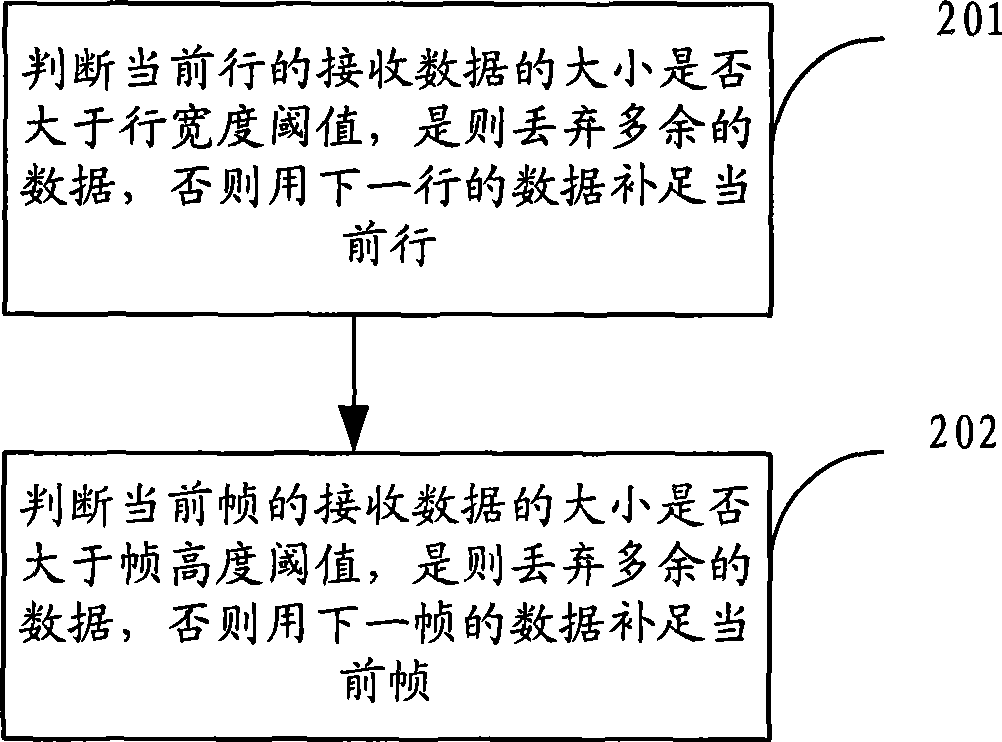
The invention provides a data error correction method for image processing systems and a device thereof, and the method comprises a row judgment step and a column judgment step. The row judgment step: whether the receiving data size of the current row is larger than the threshold of the row width is judged, if so, redundant data is dropped, otherwise the data of the next row is adopted to make up the current row; the column judgment step: whether the receiving data size of the current frame is larger than the threshold of the frame height is judged, if so, redundant data is dropped, otherwise the data of the next column is adopted to make up the current frame. The method has an advantage that dead halt or other abnormal conditions of the system caused by row data deficiency or frame data deficiency can be prevented.

Description

technical field [0001] The invention relates to a data error correction technology in an image processing system, in particular to a data error correction method and device in an image processing system. Background technique [0002] At present, the video monitoring system is more and more popular, and its main function is to monitor various live situations. It enables managers to observe the situation in all important places in the control room, such as installing cameras in important places such as entrances and exits, main passages, garages, etc., and transmits the situation in the monitoring area to the management center in real time in the form of images. You can keep track of what's going on in these important places. [0003] Since the video surveillance system generates uninterrupted data streams in real time, these uninterrupted data streams also need to be processed in real time. [0004] In the process of realizing the technical solution of the present invention...

Claims


Application Information

Patent Timeline
IPC IPC(8): H04N7/64H04N7/18H04N19/89
Inventor 冯备战
Owner WUXI ZGMICRO ELECTRONICS CO LTD
Learn More