
Circuit and method for adjusting signal bandwidth

A signal bandwidth and signal technology, applied in the field of circuits with adjustable signal bandwidth, can solve problems such as inability to achieve wideband frequency response

Inactive Publication Date: 2013-02-27
IND TECH RES INST
View PDF2 Cites 0 Cited by
  • Summary
  • Abstract
  • Description
  • Claims
  • Application Information

AI Technical Summary

Problems solved by technology

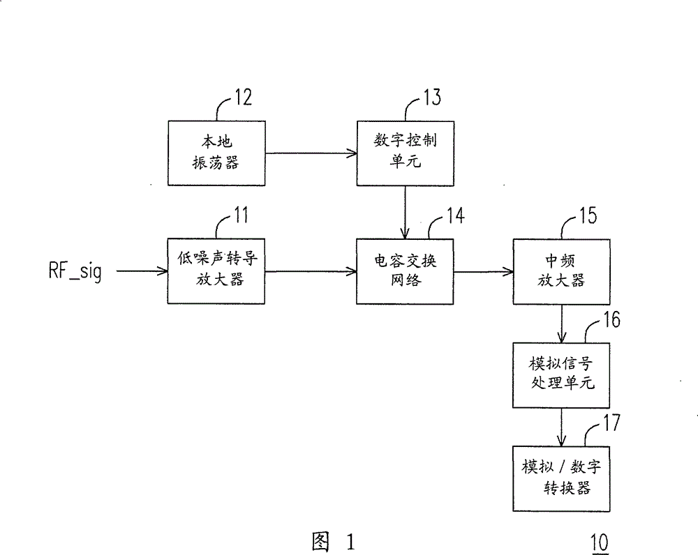
[0017] Traditional receivers 10 and 20 cannot achieve wideband frequency response, while current wireless communication receiver circuits are integrated with wideband, multi-mode and multiple standards

Method used


Image

  • Circuit and method for adjusting signal bandwidth
  • Circuit and method for adjusting signal bandwidth
  • Circuit and method for adjusting signal bandwidth

Examples


Embodiment Construction

[0084] In order to solve the problem that the frequency response of the traditional receiver is a narrow-band frequency response, the embodiments of the present invention provide a circuit with adjustable signal bandwidth and a method thereof. The circuit with adjustable signal bandwidth and its method can receive and filter wideband signals, and the bandwidth can be adjusted according to different requirements.

[0085] Please refer to Figure 8 , Figure 8 It is a circuit diagram of a circuit 80 with adjustable signal bandwidth provided by an embodiment of the present invention. Such as Figure 8 As shown, this circuit 80 includes at least one filter frequency reduction device 800, a first charging and discharging device 803, a first reset device 804, a first variable capacitance device 805, a second charging and discharging device 806, and a second reset device 807 with the second variable capacitance device 808 . Wherein, this circuit 80 adopts a dual-terminal output m...


PUM


Abstract

The invention provides a circuit with adjustable signal bandwidth, comprising a first electricity charge and discharge device, a first reset device and a first variable capacitance device; wherein, the first reset device is coupled to the first electricity charge and discharge device and the first variable capacitance device is also coupled to the first electricity charge and discharge device. The first reset device is controlled by an electricity discharge enabling signal and is used for providing a first electricity discharge route. When the first reset device is closed by the electricity discharge enabling signal, a first equivalent sum capacitance is generated by the first variable capacitance device according to n reference signals and is provided for the first electricity charge and discharge device, wherein, n is an integral number more than 0.

Description

technical field [0001] The present invention relates to a circuit of a wireless receiver and its method, and in particular to a circuit with adjustable signal bandwidth and its method. Background technique [0002] With the advancement of wireless communication technology, the structure of many wireless communication receivers is gradually moving towards the direction of thinner, smaller and power-saving. Generally speaking, the front-end circuit of the receiver needs extremely high linearity, so that the accuracy rate of the received signal demodulated and decoded by the whole receiver can be improved. [0003] The advancement of process technology has enabled many manufacturers to produce wireless communication receivers with small areas and fast speeds. However, the available power supply voltage decreases, which will lead to a decrease in the linearity of active circuits (such as: active amplifiers); on the other hand, Although the progress of the technology can reduce ...

Claims


Application Information

Patent Timeline
Patent Type & Authority Patents(China)
IPC IPC(8): H04B1/16
Inventor 黄敏峰曾明豪
Owner IND TECH RES INST
Learn More