Switch device

一种开关装置、动接触的技术,应用在电开关、信号装置、快动装置等方向,能够解决动元件插入的部分进入所述壳体的内部并粘附在所述可动触点与所述固定触点之间、触点传导故障等问题,达到消除传导故障问题、减轻滑动、改进开关性能的效果

Inactive Publication Date: 2009-08-19
KK TOKAI RIKA DENKI SEISAKUSHO +1
View PDF1 Cites 10 Cited by
  • Summary
  • Abstract
  • Description
  • Claims
  • Application Information

AI Technical Summary

Problems solved by technology

Meanwhile, for the above-mentioned common switchgear, foreign substances containing lubricating oil and inorganic and organic substances may enter the inside of the housing from the part where the moving element is inserted and adhere to the movable contact and the fixed contact. between contacts, especially due to the silicone component causing conduction failure problems between said contacts

Method used


Image

  • Switch device
  • Switch device
  • Switch device

Examples


Embodiment Construction

[0015] Hereinafter, reference will be made by applying the present invention to a brake light switch of a vehicle Figure 1-3 A description is given of its first embodiment.

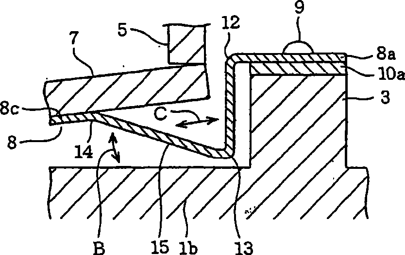
[0016] first, figure 1 The overall configuration of the vehicle stop light switch is shown, and the sealed case 1 is its main body. This hermetic case 1 is composed of a case body part 1a and a case base part 1b, and wherein said case body part 1a has a hat shape in which an upper surface part is closed by having a protrusion 2 in its central part, and The bottom is open. The housing base 1b has a planar shape, but a protrusion 3 is provided on the upper surface of the right side in the figure.

[0017] A pair of yokes 4 and 5 are provided in such a manner as to pass through the protruding portion 2 of the aforementioned case main body portion 1a. These yokes 4 and 5 are each formed of a magnetic material such as iron. Since these yokes 4 and 5 are provided by being inserted during, for example, mol...


PUM


Abstract

A switch device is provided. A movable contact positioned in a sealed case is moved together with a movable contact spring provided with an armature by a magnetic shunt body which is moved outside the sealed case. Because the movement of the magnetic shunt body is based on the change of the magnetically attracting force of a magnet with respect to the armature through a pair of yokes. The movable contact spring is provided with a bent portion which is bent in spaced-apart relation to the armature, the bent portion being provided between a fulcrum portion at a time when the movable contact spring moves and a portion where the armature is provided. The switch device moves the fixed contact and the moveable contact separated from the external substance involving into the shell of the fixed contact and moveable contact, which can quickly complete the contact of the two points and improve the switch performance and reduce the sliding contact of the relevant accessories causing the powder; the powder is not good for the contact of the fixed contact and moveable contact.

Description

technical field [0001] The invention relates to switching devices in which the actuating structure of the contacts is improved. Background technique [0002] In general, the commonly used switching device is a rod-shaped moving element arranged through a housing containing a fixed contact, a movable contact and a spring, which is usually used to make the The movable contact contacts or moves away from the fixed contact, and when the moving element is movably operated, the movable contact moves relative to the fixed contact so as to move away from or contact the fixed contact (For example, see JP-A-2005-235632). [0003] For example, the switch device having the above configuration is used as a vehicle stop light switch, and lubricating oil applied to various mechanical parts and inorganic or organic substances contained in the product exist in the vicinity of the vehicle stop light switch. Meanwhile, for the above-mentioned common switchgear, foreign substances containing ...

Claims


Application Information

Patent Timeline
Patent Type & Authority Applications(China)
IPC IPC(8): H01H5/02H01H13/20H01H13/16B60Q1/44
CPCH01H36/008H01H1/26H01H36/0046
Inventor 山田富生井手立身太田义典
Owner KK TOKAI RIKA DENKI SEISAKUSHO
Why Eureka
Try Eureka