
Locating slip support of large-span space structure

A space structure, large-span technology, applied in the direction of building structure, construction, etc., can solve the problems of limited horizontal displacement of the bearing and weakened bottom plate of the bearing, and achieve the effect of reducing the horizontal thrust, reducing the amount of steel and reliable connection.

Inactive Publication Date: 2009-08-19
HUNAN UNIV
View PDF0 Cites 12 Cited by
  • Summary
  • Abstract
  • Description
  • Claims
  • Application Information

AI Technical Summary

Problems solved by technology

In the prior art, in order to release the temperature stress and reduce the horizontal thrust of the lower support to the lower structure, the bolt holes on the bottom plate of the flat support are generally enlarged, resulting in a certain gap between the bolt and the hole wall, so that the support There can be a certain level of sliding between the seat and the supporting structure
Then, there are the following problems in the plate support that increases the bolt aperture so as to release the temperature stress: 1) the base plate of the support is weakened to a certain extent when the bolt aperture is increased; 2) the increase of the bolt aperture has a certain limit, The general hole diameter is 2 to 2.5 times the bolt diameter, so the horizontal displacement that the support can produce is very limited

Method used


Image

  • Locating slip support of large-span space structure
  • Locating slip support of large-span space structure
  • Locating slip support of large-span space structure

Examples


Embodiment

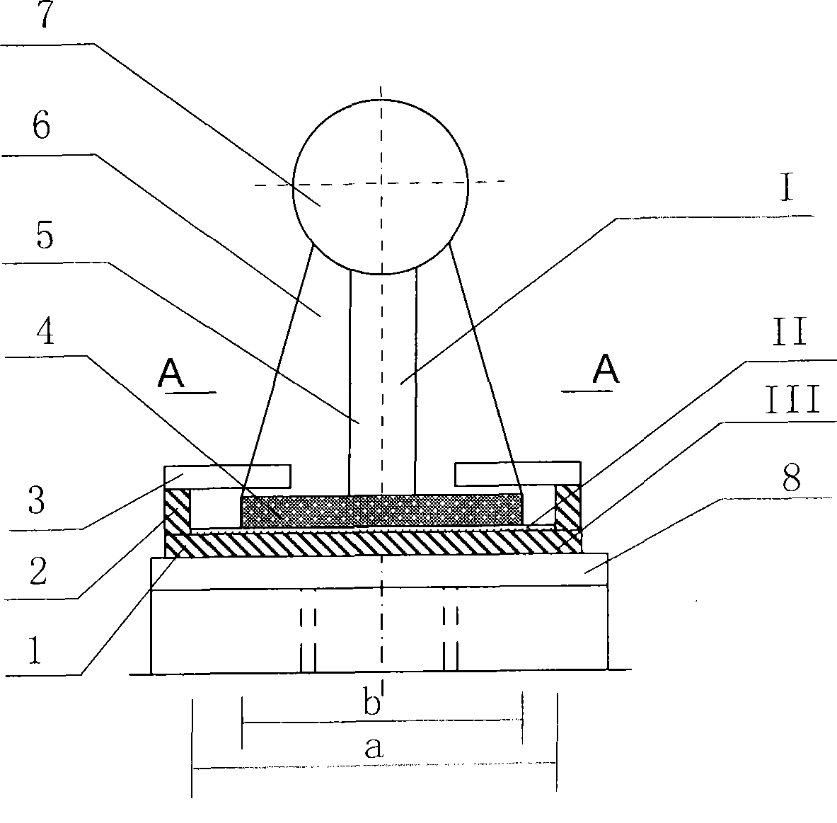
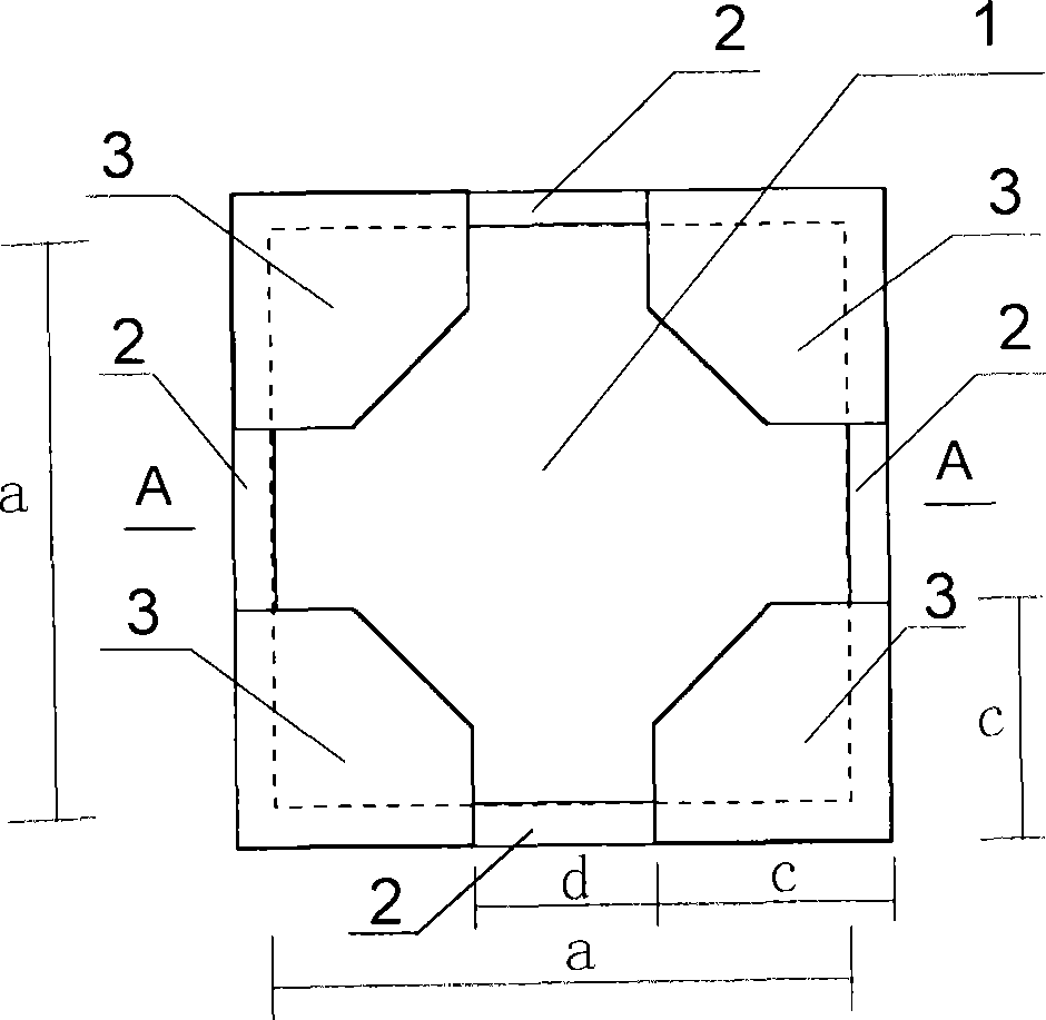
[0018] In conjunction with the accompanying drawings: the whole non-anchor bolt limit slip bearing is composed of the cube limit box III of the lower floor, the increasing slide plate II in the cube limit box and the flat plate support I above the increase slide plate. The cube limit box is connected with the pre-embedded steel plate 8 on the support structure through welds.

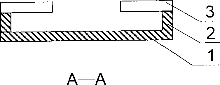
[0019] Cube limit box 1 is welded together by a square bottom plate 1 and four limit baffle plates 2 and four small cover plates 3 on the four corners of the periphery.

[0020] In this embodiment, the sliding plate II is a polytetrafluoroethylene plate with a thickness of 8 mm. The polytetrafluoroethylene plate is laid flat in the cube limiting box, and is adhered to the base plate 4 of the cube limiting box by superglue.

[0021] The flat support is provided with a vertical support pipe 5 in the middle of the base plate 4, and four cross-shaped vertical support stiffeners 6 are welded on the periphery ...


PUM

PropertyMeasurementUnit
Thicknessaaaaaaaaaa
Thicknessaaaaaaaaaa

Abstract

The invention discloses a limit gliding bearing of a large-span space structure, comprising a cubic limit box at the lower part of the bearing, an additional gliding plate arranged in the cubic limit box and a plate bearing arranged on the additional gliding plate, wherein, the cubic limit box is composed of a square base plate, 4 limit stop plates at the periphery of the square base plate and 4 small cover plates which cover the 4 corners of the 4 limit stop plates which are all welded together; the plate bearing is composed of a vertical supporting tube which is welded at the middle part of the base plate and 4 cross-shaped vertical supporting stiffening plates which are welded at the periphery of the vertical supporting tube; clearance size of the square base plate of the cubic limit box is larger than the size of the base plate of the plate bearing, and horizontal slip of the plate bearing is the difference between the clearance size of the cubic limit box and the size of the base plate of the plate bearing. In the invention, the plate bearing is allowed to have relatively large horizontal displacement, thus effectively releasing thermal stress, reducing horizontal thrust of the plate bearing on the lower structure of the limit gliding bearing, effectively reducing use amount of steel and lowering construction cost; meanwhile, in the invention, weakening on the base plate of the limit gliding bearing by opening anchor bolt holes is avoided, the structure is simple and the installation is convenient.

Description

technical field [0001] The invention relates to the field of space structures in the construction industry, in particular to a non-anchor-bolt limiting sliding support for a large-span space structure. Background technique [0002] Large-span space structures are widely used in stadiums, convention and exhibition centers, theaters, large shopping malls, industrial plants and other buildings. on the substructure. In the prior art, in order to release the temperature stress and reduce the horizontal thrust of the lower support to the lower structure, the bolt holes on the bottom plate of the flat support are generally enlarged, resulting in a certain gap between the bolt and the hole wall, so that the support A certain amount of horizontal slip can occur between the seat and the supporting structure. Then, there are the following problems in the plate support that increases the bolt aperture so as to release the temperature stress: 1) the base plate of the support is weakene...

Claims


Application Information

Patent Timeline
IPC IPC(8): E04B1/36E04B1/342
Inventor 贺拥军周绪红
Owner HUNAN UNIV
Learn More