
Wireless communication system, communication control method and communication node

A wireless communication system and wireless node technology, applied in the field of wireless communication systems, communication control methods and communication nodes, can solve the problems of occupation, inability to guarantee reliable maintenance of wireless communication routes, difficult access control, etc.

Inactive Publication Date: 2009-08-12
PANASONIC CORP
View PDF1 Cites 21 Cited by
  • Summary
  • Abstract
  • Description
  • Claims
  • Application Information

AI Technical Summary

Problems solved by technology

The star topology lacks flexibility in its structure, and it has the disadvantage that it is used under the assumption of the topology when the mobile node performs communication
[0020] In the case of periodically transmitting short data (data of small data volume), there is a limit to the amount of information exchanged between two nodes by a single data transmission and reception
In this case, the amount of information transferred through multiple data transfers and receptions can be increased, however, it must be ensured that wireless communication does not cause collisions in data transfers
However, the simplified protocol was not structured to avoid the possibility of collisions in data transfers and cannot guarantee reliable maintenance of wireless communication routes
[0021] Also, according to IEEE 802.15.4, GTS's guarantee of slots is defined in a superframe period, and the problem arises in that there is a limit (upper limit) to the number of slots reserved for slots within a single superframe period
Also, a regulator for managing slot reservations is required, and there is also the problem that there may be constraints on the network structure
The network topology limited by IEEE 802.15.4 is not suitable for the case of performing data transmission and reception between MNs by P2P (Peer-to-Peer)
[0022] According to the system disclosed in Patent Document 1, the startup time of the receivers of the peripheral nodes can be synchronized uniformly by defining the wake-up signal to ensure data transmission and reception, but the problem is that the channel occupation period (from transmitting the wake-up signal to During the channel occupation period, the wake-up signal transmitted by a node before the start of data transmission occupies the channel
As a result, the probability of signal collision may increase, and it is difficult to have sufficient access control (collision avoidance control) between transmission nodes

Method used


Image

  • Wireless communication system, communication control method and communication node
  • Wireless communication system, communication control method and communication node
  • Wireless communication system, communication control method and communication node

Examples


no. 1 example

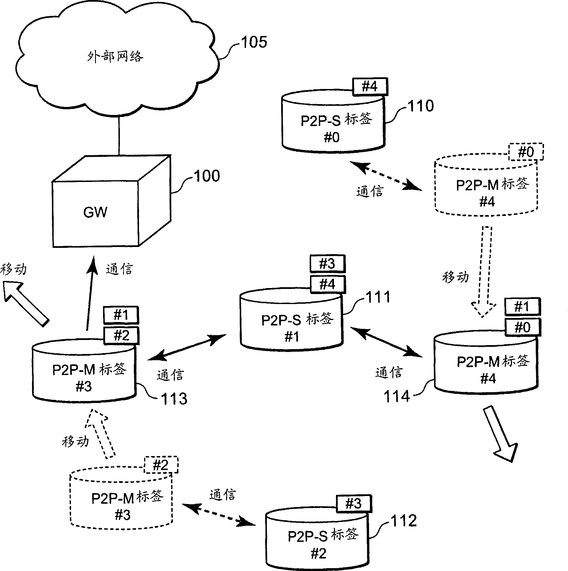
[0126] First, refer to figure 1 , a description will be given about a communication system including different types of wireless nodes in the first embodiment of the present invention. figure 1 is a schematic diagram showing an example of a communication system including different types of wireless nodes in the first embodiment of the present invention.

[0127] figure 1 The communication system shown in includes a gateway (GW) 100 and a plurality of wireless nodes (wireless tags) 110-114. The GW 100 is connected to an external network such as the Internet via wired / wireless means, and it is a communication node that can communicate with the external network 105 . Ideally, the GW 100 is fixed at a location where power required for operation can be supplied via a given wiring.

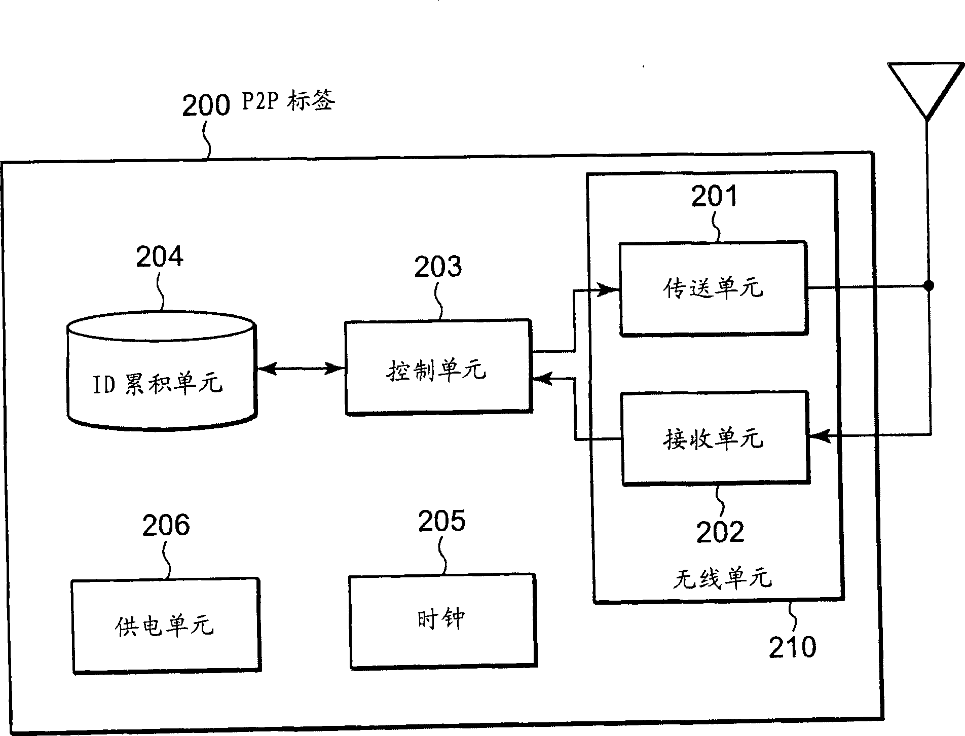
[0128] On the other hand, each of the wireless tags 110 to 114 is a battery-driven small wireless tag (active electronic tag), and it is a communication node that can transmit and receive frames, ...

no. 2 example

[0192] Next, a description will be given about a second embodiment of the present invention. Figure 9 is a schematic diagram illustrating a wireless communication network including a plurality of nodes 1 to 4 in the second embodiment of the present invention. exist Figure 9 In , each of the plurality of nodes is a wireless communication node that can directly communicate with other nodes present in the vicinity (within the wireless propagation range) of each of the nodes 1 to 4 . Each of the nodes 1 to 4 can change the node with which it can communicate when it moves. Nodes 1 to 4 may be mobile, or may be fixed.

[0193] Nodes 1 to 4 are nodes that perform wireless communication, as described above. Each of these nodes is a node that automatically starts and stops a receiver (may be referred to as "Rx" hereinafter) of a wireless unit. In the schedule of starting and stopping, by performing synchronization between nodes, each node can have the same schedule.

[0194] Eac...


PUM


Abstract

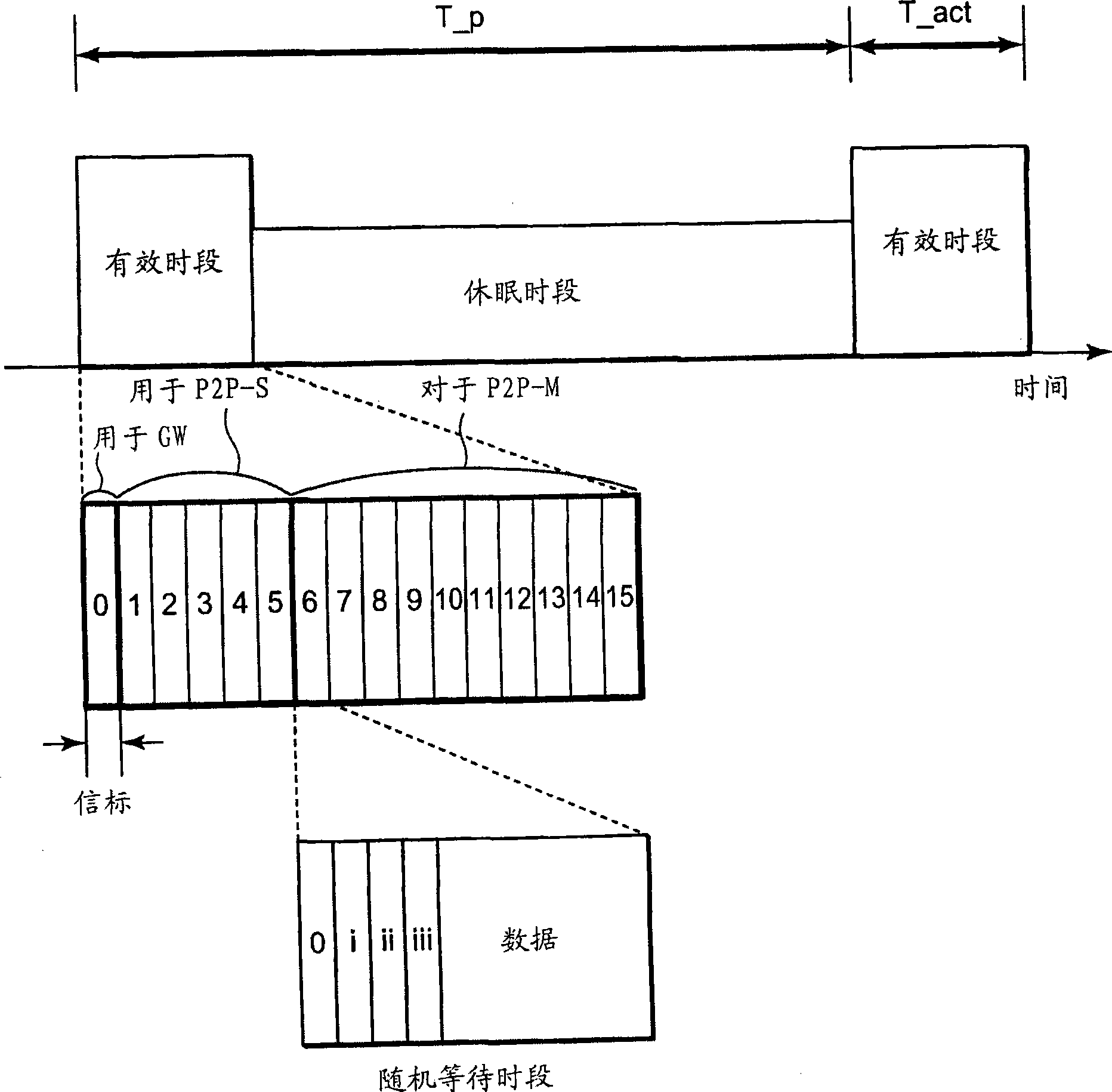
A technique is disclosed which achieves both a reduction of the power consumption and an efficient access control at each of wireless nodes in a wireless communication system. According to this technique, a given period at the beginning of which a beacon is transmitted from a gateway (GW) (100) is specified that it is divided into an active interval during which each wireless node (P2P tag) transmits / receives frames and a sleep interval during which the frame transmission / reception operations are inactive. Further, the active interval is divided into a plurality of timeslots having a fixed length, and in particular, divided into intervals during which different types, that is, the GW, fixed nodes (P2P-S tags) and mobile nodes (P2P-M tags) may perform their respective frame transmissions. Each P2P tag selects, from the intervals of its own type, a timeslot at random and uses the selected timeslot to be on standby for a random standby time and then transmit a frame including information to be used for determining the ID of that P2P tag, the selected timeslot and the standby time.

Description

technical field [0001] The present invention relates to a wireless communication system, a communication control method and a communication node. In particular, the present invention relates to a wireless communication system, a communication control method, and a communication node for realizing Medium Access Control (MAC) with low power consumption in the case of bi-directional exchange of data by a mobile communication node. Background technique [0002] In wireless hardware of a wireless system, reduction of power consumption is an important factor. Specifically, in a wireless communication system, as examples of applications requiring a power saving mechanism, there are active electronic tag systems, sensor network systems, and the like. For sensor nodes in active electronic tags, or in sensor networks, portability and easy and flexible installation are important characteristics. Typically, it is a battery type node with a small size battery. [0003] Applications su...

Claims


Application Information

Patent Timeline
IPC IPC(8): H04L12/28H04L7/00
CPCY02B60/50Y02D30/70
Inventor 川上哲也横堀充宫本和彦铃木良宏
Owner PANASONIC CORP
Learn More