
Power converter for switch reluctance motor

A technology of switched reluctance motors and power converters, which is applied in the direction of speed/torque control of a single motor, and can solve problems such as limiting the application of switched reluctance motors, reducing system utilization, and increasing system volume and weight, so as to reduce losses, Effects of improving reliability and reducing motor loss

Inactive Publication Date: 2009-08-12
NANJING UNIV OF AERONAUTICS & ASTRONAUTICS
View PDF0 Cites 11 Cited by
  • Summary
  • Abstract
  • Description
  • Claims
  • Application Information

AI Technical Summary

Problems solved by technology

This method increases the volume and weight of the system, reduces the utilization rate of the system, and limits the application of switched reluctance motors in this field

Method used


Image

  • Power converter for switch reluctance motor
  • Power converter for switch reluctance motor
  • Power converter for switch reluctance motor

Examples


Embodiment Construction

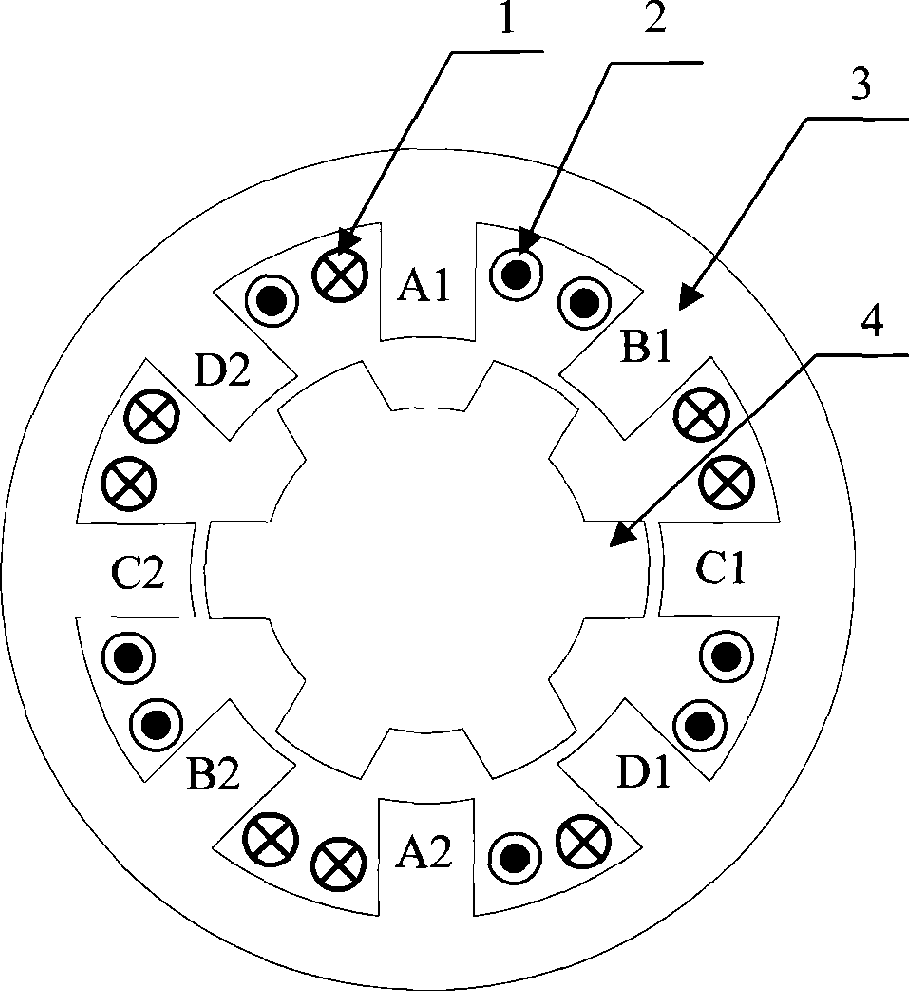
[0014] Such as figure 1 shown. Take the 8 / 6-pole switched reluctance motor as an example for illustration. The windings A1 and A2 are connected in series or in parallel to form the A-phase winding, the windings B1 and B2 are connected in series or in parallel to form the B-phase winding, the windings C1 and C2 are connected in series or in parallel to form the C-phase winding, and the windings D1 and D2 are connected in series or in parallel to form the D-phase winding. A1 ~ A4, B1 ~ B4 windings are connected in the way of NSNSNSSNSNSNSN.

[0015] The power converter of the 8 / 6-pole switched reluctance motor includes 4 H-bridge circuits, 4 fuses and bus bars, wherein the first H-bridge circuit includes four diodes, namely the first diode D1 to the fourth diode D4 , four power switch tubes, that is, the first power switch tube V1 to the fourth power switch tube V4, the negative poles of the bus are respectively connected to the anode of the second diode D2, the anode of the f...


PUM


Abstract

The invention discloses a switched-reluctance-motor power converter with redundancy function. For an n-phase switched reluctance motor, the power converter divides a positive terminal of a power supply bus into n strands, wherein each strand is connected with a fuse wire; the other end of each fuse wire is connected with power topology of an H bridge; and negative terminals of the H bridge are gathered together. The phases of the power converter are mutually independent, and certain phase breaking down can be automatically cut off without affecting the operation of the other phases. During normal operation, the power converter can provide bipolar power so as to reduce the loss of the motor. When a power tube of the certain phase breaks down, the power converter can provide unipolar current so as to improve the system reliability of the switched reluctance motor.

Description

technical field [0001] The invention relates to a power converter, in particular to a power converter for a switched reluctance motor. Background technique [0002] Switched reluctance motors have the advantages of simple structure, firmness, reliable operation, flexible control, high operating efficiency, strong fault tolerance, adaptability to high temperature and high speed, etc., and have strong competitiveness in the aerospace field. Most of the switched reluctance motors currently used in the aerospace field use the traditional asymmetrical half-bridge topology for unipolar power supply, and use redundant backup methods to meet the special requirements for reliability in these occasions. This method increases the volume and weight of the system, reduces the utilization rate of the system, and limits the application of the switched reluctance motor in this field. Contents of the invention [0003] The technical problem to be solved by the present invention is to prop...

Claims


Application Information

Patent Timeline
Patent Type & Authority Applications(China)
IPC IPC(8): H02P6/08
Inventor 彭晶晶邓智泉王晓琳陈小元
Owner NANJING UNIV OF AERONAUTICS & ASTRONAUTICS
Learn More