
Substitution control method for air conditioner fault sensor

A fault sensor and alternative control technology, applied in heating and ventilation control systems, heating methods, space heating and ventilation, etc., can solve problems such as the impact of users' daily use, and achieve the effect of avoiding inconvenience and improving comfort

Active Publication Date: 2009-08-12
广东科龙嘉科电子有限公司
View PDF0 Cites 43 Cited by
  • Summary
  • Abstract
  • Description
  • Claims
  • Application Information

AI Technical Summary

Problems solved by technology

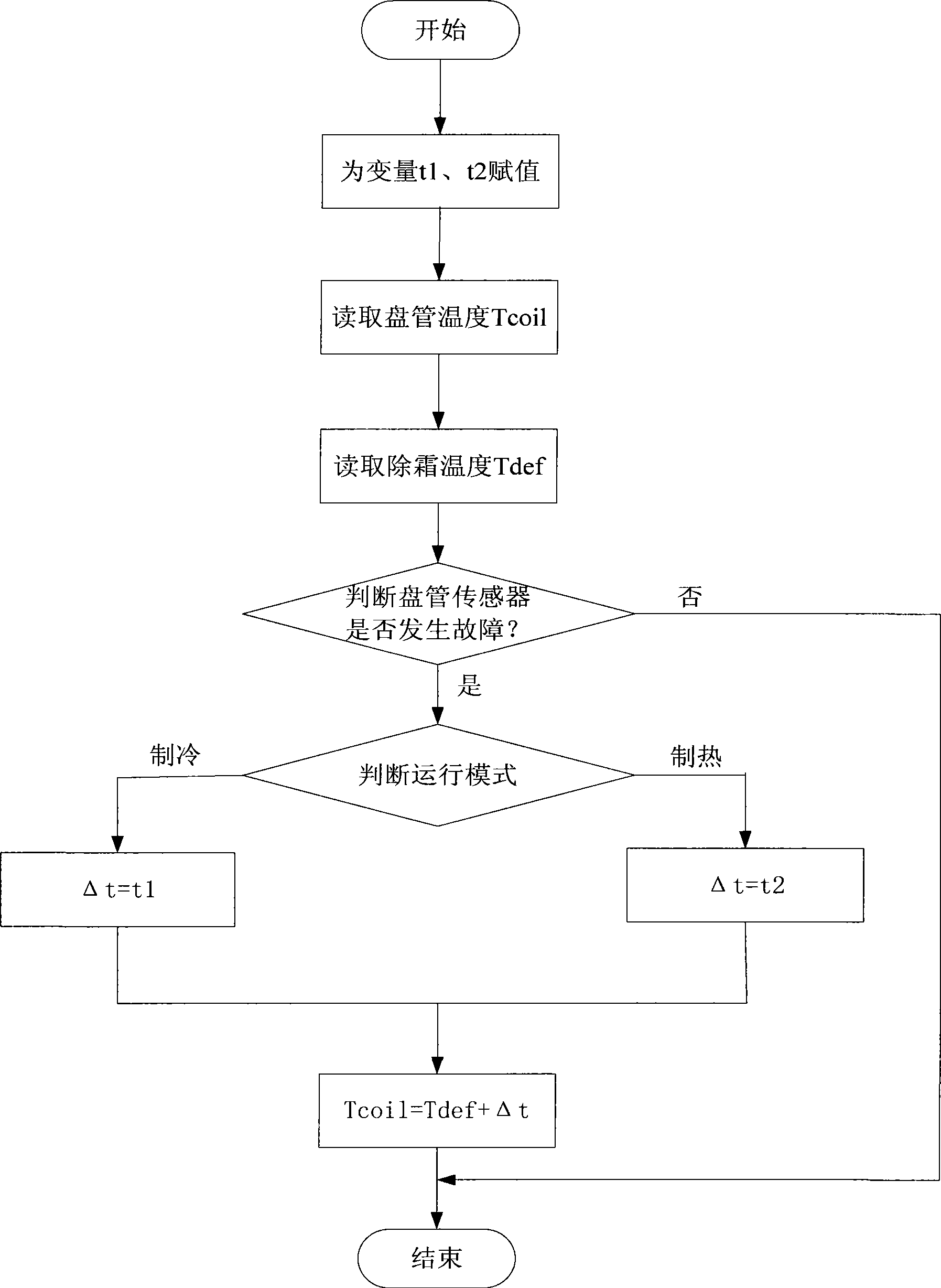
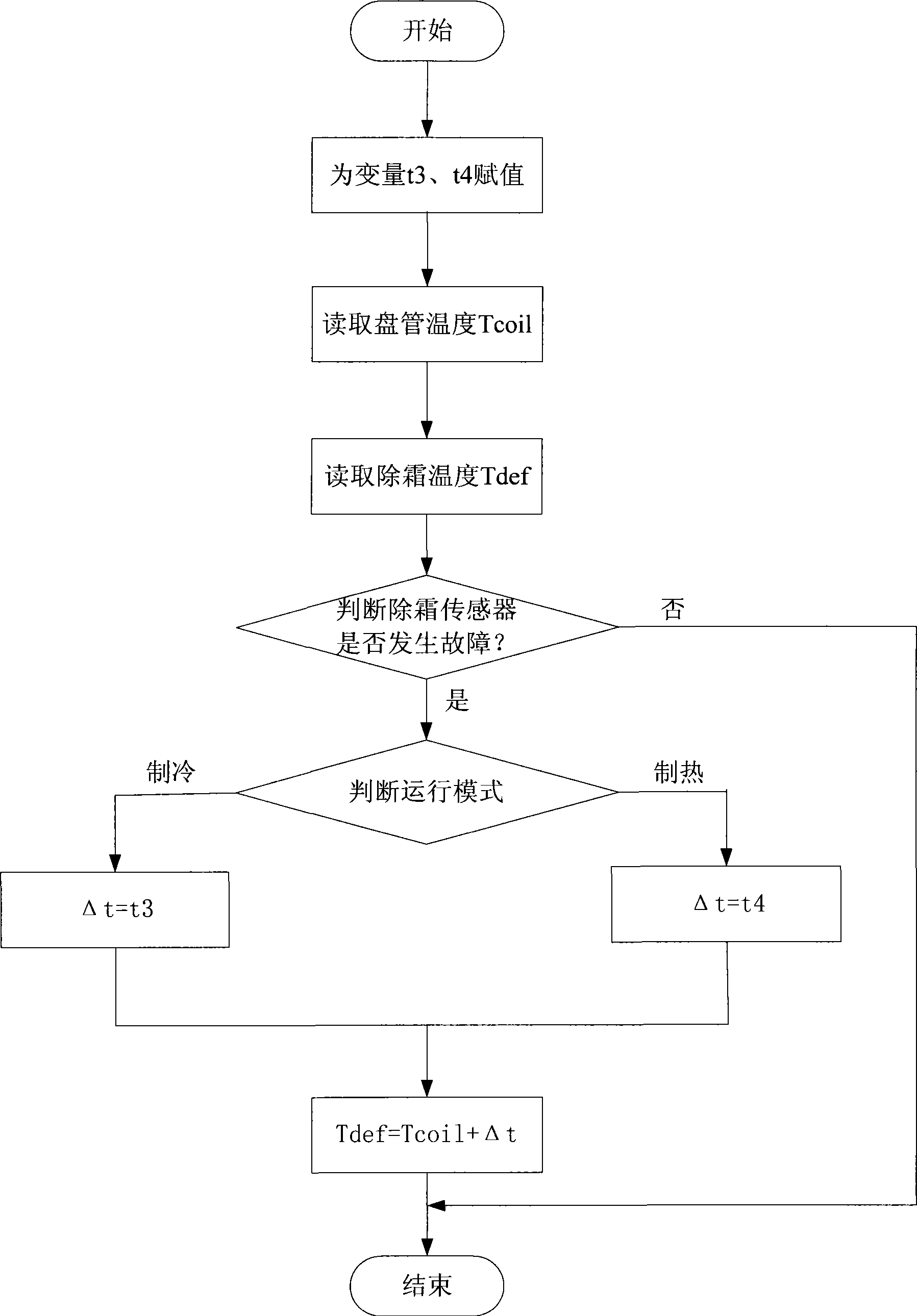
[0003] In order to solve the problem that the existing air conditioner adopts the way of shutting down and reporting errors to affect the daily use of users when the sensor fails, the present invention proposes an alternative control method for the failure sensor of the air conditioner. When a certain sensor fails, the main The control module can temporarily use the data measured by other sensors to replace the measured value of the faulty sensor after correction to participate in the control calculation, so as to ensure that the air conditioner can continue to run

Method used


Image

  • Substitution control method for air conditioner fault sensor
  • Substitution control method for air conditioner fault sensor

Examples


Embodiment 1

[0024] Embodiment 1, this embodiment discloses an alternative control method when the coil temperature sensor fails, that is, when the condenser coil temperature sensor fails, read the detection value of the defrosting temperature sensor set on the condenser , recorded as Tdef; the detection value Tdef is corrected, that is, after adding a correction value Δt, to replace the detection value of the coil temperature sensor, recorded as Tcoil; and then Tcoil and Tdef are substituted into the main control program to participate in the control calculation, so that Realize the continuous operation of the main control program, so that the whole unit can achieve the purpose of non-stop operation while alarming and waiting for repair, so as to facilitate the use of users.

[0025] Since the detection values ​​output by the coil temperature sensor and the defrosting temperature sensor are generally analog signals, after being received by the analog-to-digital conversion module inside the...

Embodiment 2

[0040] Embodiment 2, this embodiment discloses an alternative control method when the defrosting temperature sensor fails, that is, when the defrosting temperature sensor of the condenser fails, read the detection value of the coil temperature sensor set on the condenser , denoted as Tcoil; the detection value Tcoil is corrected, that is, after adding a correction value Δt, to replace the detection value of the defrosting temperature sensor, denoted as Tdef; then Tcoil and Tdef are substituted into the main control program to participate in the control calculation, In this way, the main control program can be continuously operated, so that the whole unit can achieve the purpose of continuous operation without stopping the machine while alarming and waiting for repair.

[0041] As in Embodiment 1, the detection values ​​Tcoil and Tdef may refer to specific temperature values ​​corresponding to the analog voltage signals output by the coil temperature sensor and the defrosting te...


PUM


Abstract

The invention discloses a substitution and control method for a fault sensor of an air conditioner, which is suitable for a coil pipe temperature sensor and a defrosting temperature sensor for respectively detecting the saturation temperature of a condenser and the whether the condenser is defrosting or not in an outdoor unit of the air conditioner. When the coil pipe temperature sensor has fault, the detecting value of the defrosting temperature sensor substitutes the detecting value of the coil pipe temperature sensor by a correcting method, and participates in the control and calculation of a main control program; and when the defrosting temperature sensor has fault, the detecting value of the coil pipe temperature sensor substitutes the detecting value of the defrosting temperature sensor by the correcting method, and participates in the control and calculation of the main control program, thereby ensuring that the unit can continuously run while reporting the error and waiting for maintenance, further avoiding the inconvenience brought to users caused by disorderly closedown and improving the service comfort of products.

Description

technical field [0001] The invention belongs to the technical field of air conditioning and refrigeration engineering, and in particular relates to an alternative control method that adopts an alternative method to ensure continuous operation of the air conditioner when a certain sensor in the air conditioner fails. Background technique [0002] Air conditioners, especially one-to-multiple air conditioners, their main control program needs to use the parameter values ​​measured by the temperature sensors distributed at each control point in the refrigeration system to participate in control calculations or judgments during operation, so as to perform calculations or judgments based on the calculation or judgment results. Realize the control of compressors, electronic expansion valves, fans and other components. If a sensor breaks down, the main control program will judge and calculate due to the lack of necessary temperature parameter values, so that normal operation control...

Claims


Application Information

Patent Timeline
IPC IPC(8): F24F11/00
Inventor 吴林涛郭富军
Owner 广东科龙嘉科电子有限公司
Learn More