
Straw crushing device with combined bed knife

A crushing device and bottom knife technology, which is applied in cutting equipment, grain processing, agricultural machinery and implements, etc., can solve the problems of affecting the shearing effect, jamming between cutter heads, reducing shearing uniformity, etc., and achieve smooth crushing process , Shock vibration is small, and the effect of improving uniformity

Inactive Publication Date: 2009-08-12
JIANGSU DATANG MACHINERY
View PDF0 Cites 8 Cited by
  • Summary
  • Abstract
  • Description
  • Claims
  • Application Information

AI Technical Summary

Problems solved by technology

In this structure, the cutting surface of the flying blade is perpendicular to the direction of the knife roller rotation axis, so it can only produce a good shearing effect on the straw fed in the longitudinal direction, but cannot effectively cut the straw fed in the horizontal direction. , which affects the shearing effect and reduces the uniformity of shearing; in addition, when the fed straw is messy, it is easy to cause the jamming between the cutter heads, which affects the normal operation of the crushing process.

Method used


Image

  • Straw crushing device with combined bed knife
  • Straw crushing device with combined bed knife
  • Straw crushing device with combined bed knife

Examples


Embodiment Construction

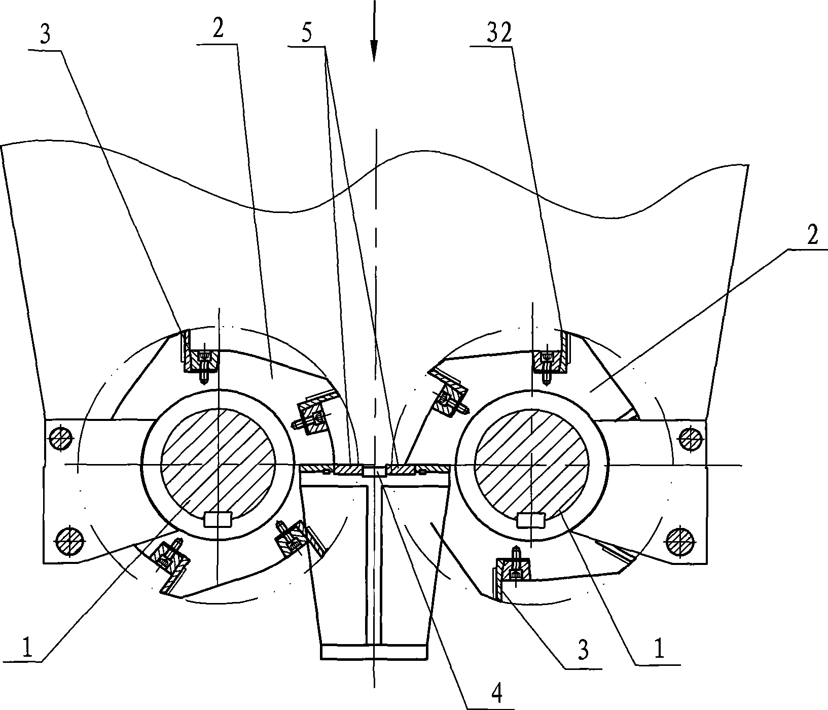
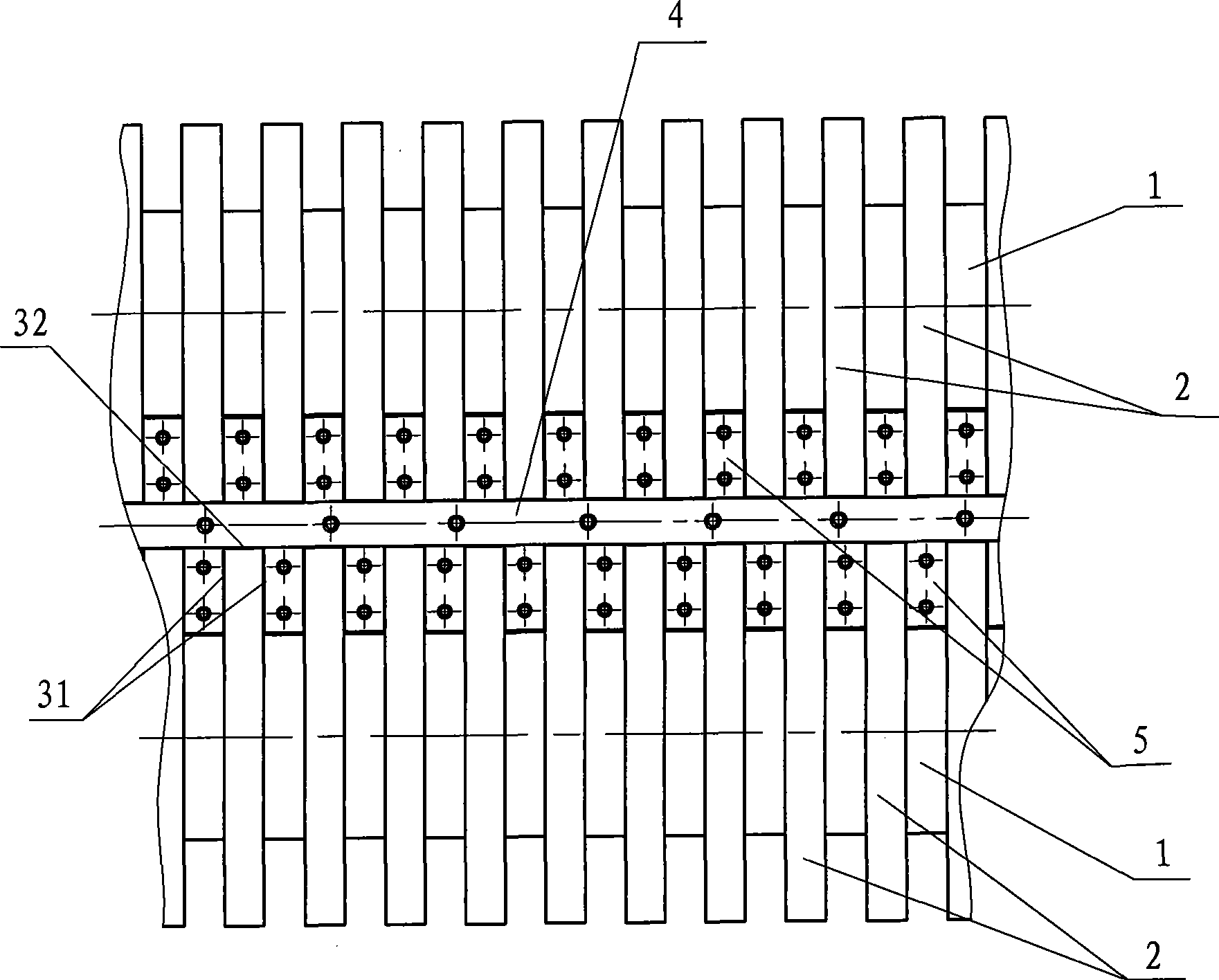
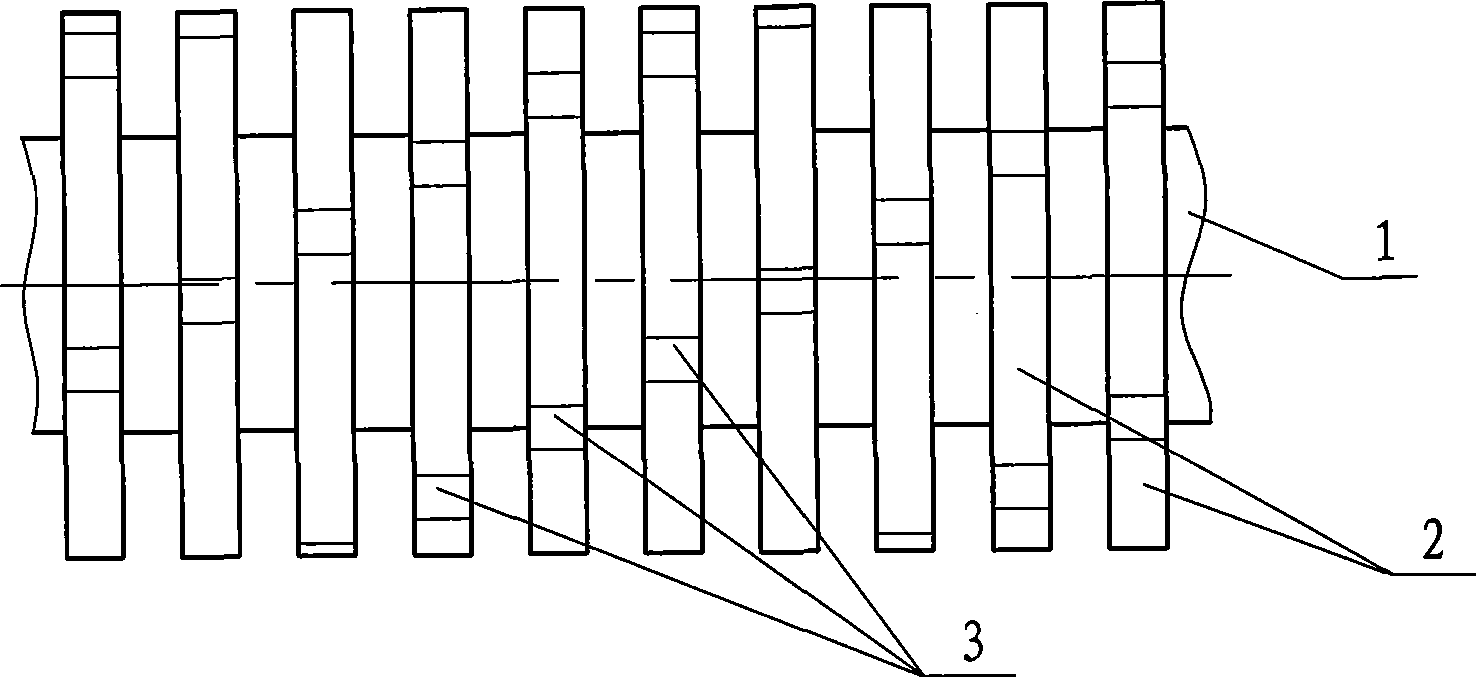
[0011] Such as figure 1 , figure 2 As shown, the embodiment of the present invention has two cutter rollers 1 arranged side by side, and a plurality of cutterheads 2 are arranged at intervals along the axial direction on the cutter rollers, and a plurality of flying blades 3 are uniformly arranged on the circumference of the cutterheads. The two side edges of the flying blade have transverse blades 31, and the radially outer edge of the flying blade has a longitudinal blade 32; a longitudinal vertical bottom knife 4 is arranged between the two knife rollers, and two sets of horizontally extending knives are arranged on both sides of the vertical bottom knife. The horizontal bottom knife 5 in the space between the discs. In the course of work, the horizontal blade 31 of the flying blade cooperates with the horizontal bottom knife 5 to effectively shear the straw fed vertically, and the vertical blade 32 of the flying blade cooperates with the vertical bottom knife 4 to effect...


PUM


Abstract

The present invention relates to a crushing processing device which is used for plant stalk in the industries of papermaking, clean energy, etc. Specifically the invention relates to a combined dead knife straw crusher. The device comprises at least one rotatable knife roll which is arranged with a plurality of knife discs. The circumferences of knife discs are uniformly installed with a plurality of fly knife blades. The edges of two sides of each fly knife blade are provided with transverse cutting edges. The radial outer margin of each fly knife blade is provided with a longitudinal cutting edge. The side part of knife roll is fixed with a longitudinal dead knife in longitudinal direction. The rotation track of longitudinal cutting edge of fly knife blade is next to the longitudinal edge of longitudinal dead knife so that the longitudinal cutting edge and the longitudinal dead knife can execute relative shearing movement. The side of knife roll next to the longitudinal is also fixedly installed with a plurality of transverse dead knifes which are transversely installed and are positioned in the clearance between the adjacent knife discs, so that the transverse cutting edges of fly knife blades and the transverse dead knifes can execute relative shearing movement. The crushing processing device of the invention greatly increases the homogeneity of crushing and simultaneously has the advantages of smooth crashing process, little impact vibration and high reliability.

Description

technical field [0001] The invention relates to a crushing and processing equipment for plant stems used in industries such as papermaking and clean energy, in particular to a combined bottom knife straw crusher. Background technique [0002] The existing more commonly used straw crushing device generally includes a pair of cutter rollers installed in the crushing chamber, and a plurality of cutter heads are arranged at intervals along the axial direction on each cutter roller, and a plurality of cutter heads are evenly arranged on the circumference of the cutter head. Flying blades, the cutter discs on the two cutter rollers are interlaced with each other, during the working process, the cutter discs on the two cutter rollers perform relative shearing motion, and the straw is sheared and broken by the side edge of the flying blades. In this structure, the cutting surface of the flying blade is perpendicular to the direction of the knife roller rotation axis, so it can only ...

Claims


Application Information

Patent Timeline
Patent Type & Authority Applications(China)
IPC IPC(8): A01F29/06B02C18/06B02C18/18
Inventor 唐浩
Owner JIANGSU DATANG MACHINERY
Learn More