Multi-fingered robot hand
A robotic hand, palm technology, applied in robotics, medical science, artificial arms, etc., can solve problems such as poor stability
- Summary
- Abstract
- Description
- Claims
- Application Information
AI Technical Summary
Problems solved by technology
Method used
Image
Examples
Embodiment 1
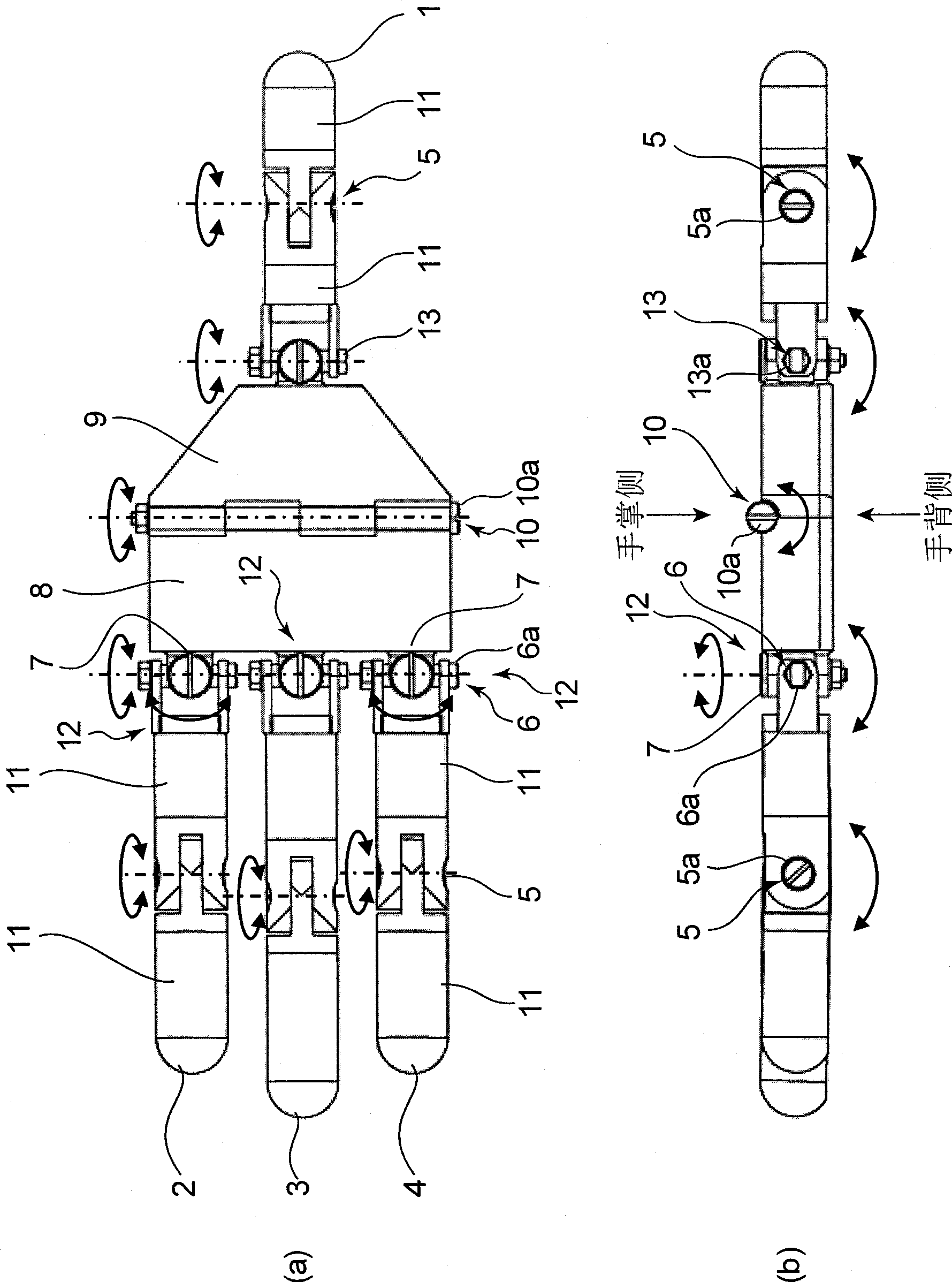
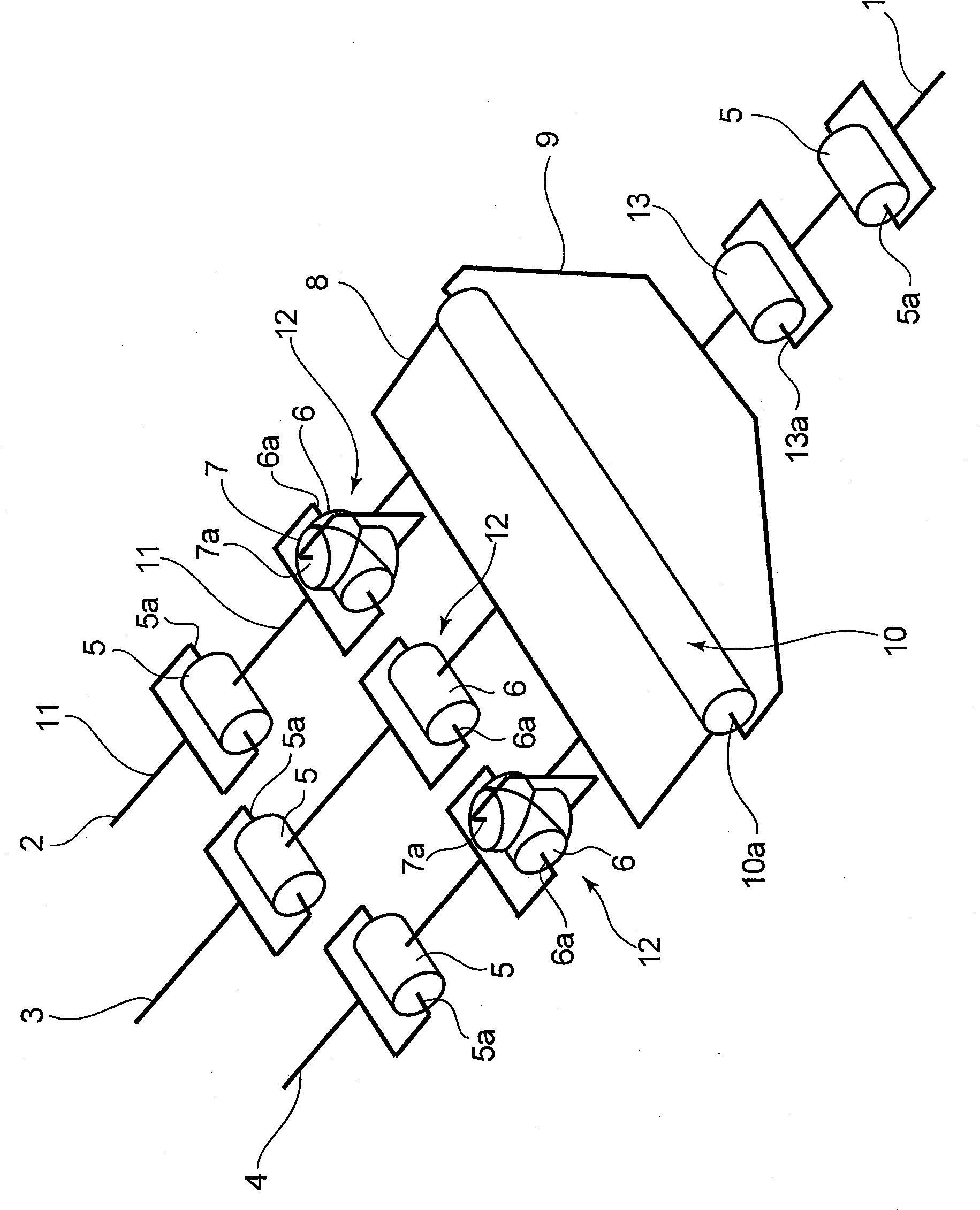
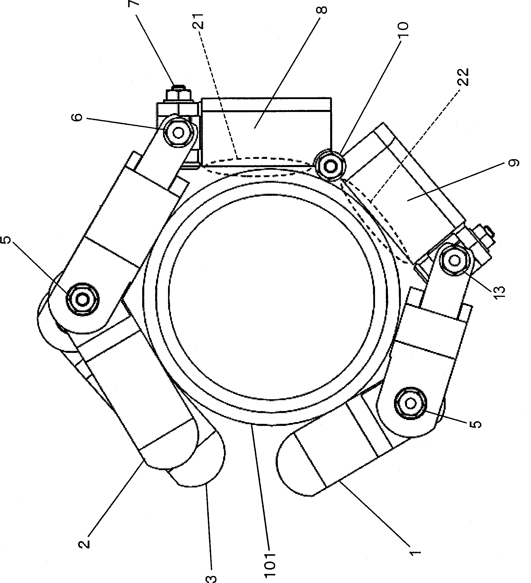
[0028] figure 1 (a) and (b) show an embodiment of the multi-fingered robotic hand of the present invention. As shown in the figure, the robot hand of this embodiment has four finger mechanisms 1 , 2 , 3 and 4 , among which three finger mechanisms 2 , 3 and 4 (the first finger mechanism) and another finger mechanism 1 ( The second finger mechanism) holds the object from both sides. The finger mechanism 1 corresponds to the thumb, the finger mechanism 2 corresponds to the index finger, the finger mechanism 3 corresponds to the middle finger, and the finger mechanism 4 corresponds to the ring finger.
[0029] The robot hand includes a first palm portion 8 connected with the finger mechanisms 2 , 3 , and 4 , a second palm portion 9 connected with the finger mechanism 1 , and one of the connecting portions that connect the first palm portion 8 and the second palm portion 9 . Example of the palmar joint 10. That is, in the present embodiment, the connecting portion has one palm ...
Embodiment 2
[0058] Figure 7 (a) and (b) are schematic diagrams showing a multi-fingered robotic hand according to Embodiment 2 of the present invention. In the second embodiment, an elastic convex member 51 is provided on the palm side surface of the second palm portion 9 of the first embodiment, and other structures and driving methods are the same as those in the first embodiment.
[0059] Figure 7 The elastic protruding member 51 shown in (a) and (b) is integrally formed with the elastic skin member described in Example 1 so as to substantially cover the center portion of the palm side surface of the second palm portion 9 . The material is the same as that of the elastic skin parts, such as rubber, polyurethane, silicon, sponge, etc. In addition, in this case, considering the contactability with the article, it is preferable that the rubber hardness is about 20 degrees to 30 degrees Hs (Hardness Spring).
[0060] When the elastic protruding part 51 holds the object in the multi-fi...
Embodiment 3
[0064] Figure 8 (a) to (c) are schematic diagrams showing the multi-fingered robot hand according to the third embodiment of the present invention. In this embodiment, the palm side surface of the palm 9 of the first embodiment is provided with a bag member 55 that expands and contracts based on the entry and exit of fluid, and the other structures and driving methods are the same as those of the first embodiment.
[0065] Figure 8 The bag member 55 shown in (a) to (c) is formed separately from the elastic skin member described in Embodiment 1 so as to substantially cover the center portion of the palm-side surface of the second palm portion 9 . The material thereof is stretchable material such as rubber. Moreover, as a fluid which enters and exits the bag member 55, gas, such as compressed air, or liquid, such as water, is mentioned, for example.
[0066] Multi-fingered robotic hands such as image 3 , Figure 4 In the case of actively using the palm side surfaces of t...
PUM
 Abstract
Description
Claims
Application Information
 - R&D
- Intellectual Property
- Life Sciences
- Materials
- Tech Scout
- Unparalleled Data Quality
- Higher Quality Content
- 60% Fewer Hallucinations
Browse by: Latest US Patents, China's latest patents, Technical Efficacy Thesaurus, Application Domain, Technology Topic, Popular Technical Reports.
© 2025 PatSnap. All rights reserved.Legal|Privacy policy|Modern Slavery Act Transparency Statement|Sitemap|About US| Contact US: help@patsnap.com


