Encapsulation employing optical hardening glue

A packaging method and a technology of hardening glue, which is applied in the manufacture of electrical components, electrical solid devices, semiconductor/solid devices, etc., can solve problems such as damage, increased cost, and limited mechanical strength, and achieve cost reduction, mechanical strength improvement, and low-cost materials Effect

Inactive Publication Date: 2010-09-22
LINGSEN PRECISION INDS
View PDF2 Cites 0 Cited by
  • Summary
  • Abstract
  • Description
  • Claims
  • Application Information

AI Technical Summary

Problems solved by technology

[0003] However, the cover 6 is generally made of glass and is easily damaged due to external shocks; in other words, this packaging method has limited mechanical strength in the overall structure and has the problem of not being able to protect the chip 4 reliably.
Furthermore, if the thickness of the cover 6 is increased in order to improve the mechanical strength of the cover 6, the operation performance of the chip 4 will be affected; in addition, if the thickness of the shield 1 is increased to improve the mechanical strength, it will be It will lead to the increase of the overall volume and the problem of increasing the cost

Method used


Image

  • Encapsulation employing optical hardening glue
  • Encapsulation employing optical hardening glue
  • Encapsulation employing optical hardening glue

Examples


Embodiment Construction

[0020] In order to describe in detail the features and effects of the present invention, the following preferred embodiments are given below and are described as follows in conjunction with the accompanying drawings, wherein:

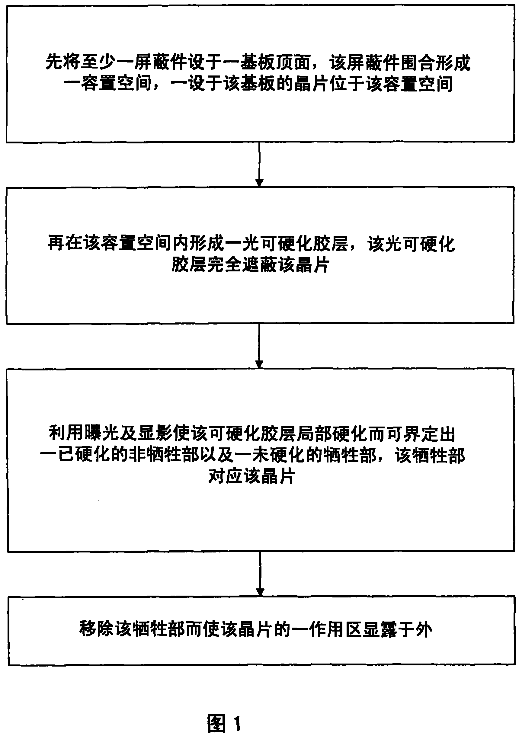
[0021] figure 1 It is an action flowchart of a preferred embodiment of the present invention.

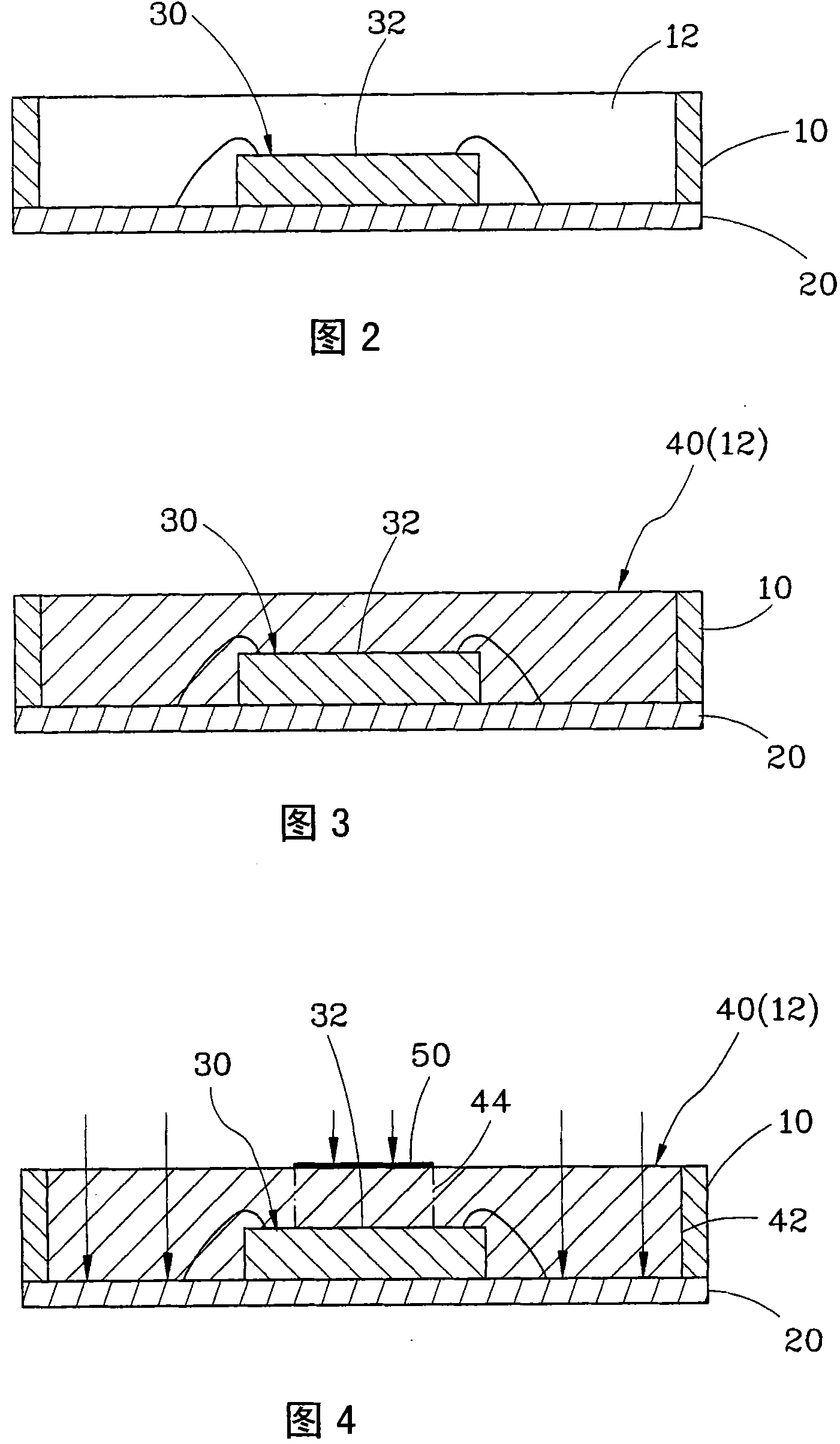
[0022] figure 2 It is a schematic diagram of the processing of a preferred embodiment of the present invention, mainly revealing the state before the formation of the photohardenable adhesive layer.

[0023] image 3 It is a processing schematic diagram of a preferred embodiment of the present invention, mainly revealing the state after the photohardenable adhesive layer is formed.

[0024] Figure 4 It is a schematic diagram of the processing of a preferred embodiment of the present invention, mainly revealing the state of the photohardenable adhesive layer under exposure.

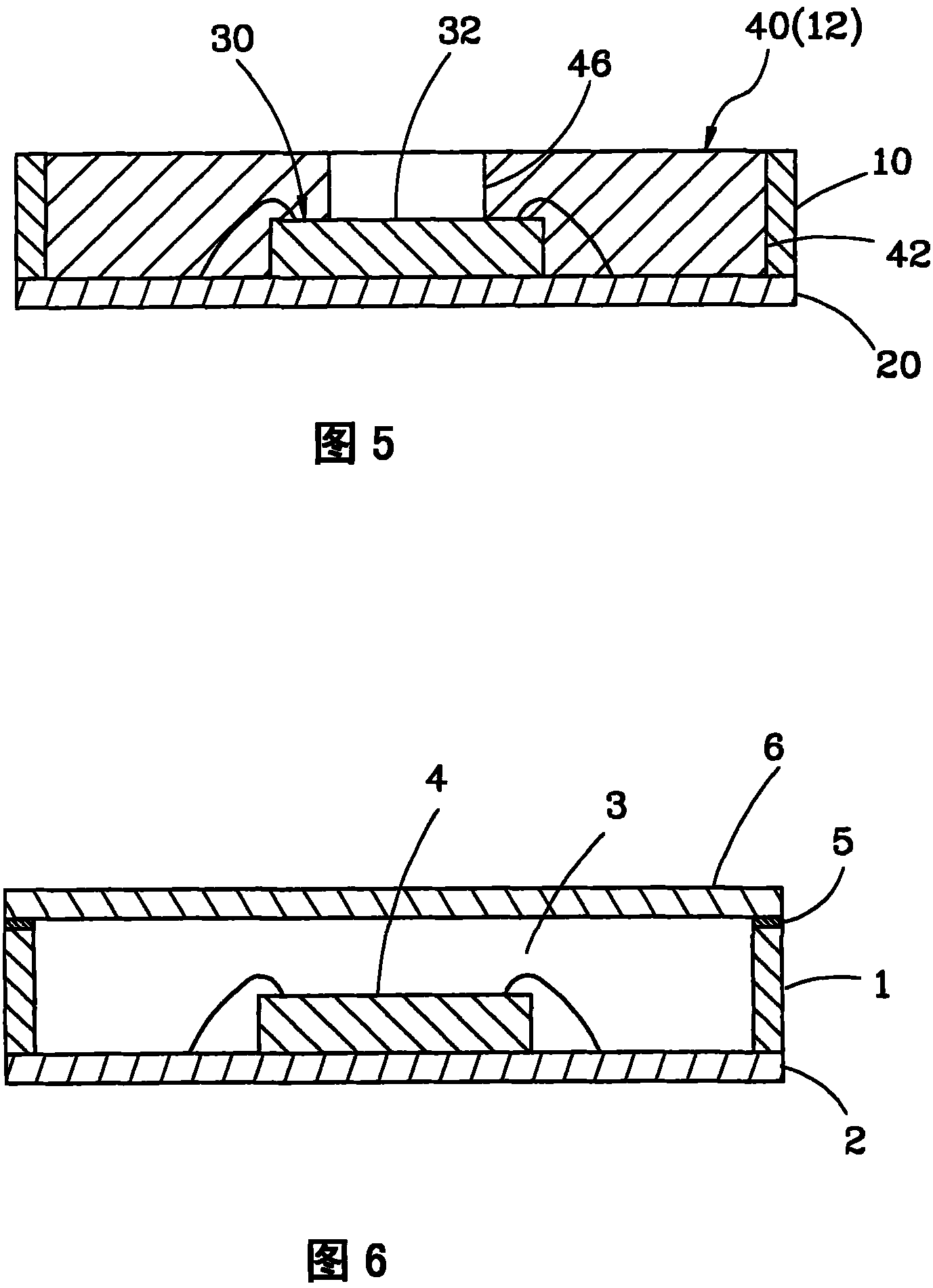
[0025] Figure 5 It is a processing schematic diagram of a preferred embodim...


PUM


Abstract

The invention discloses a packaging method which uses light hardenable adhesive, including the following steps: a) at least one shield piece is arranged on the top surface of a substrate; the shield piece forms an accommodation space by surrounding; and a chip arranged on the substrate is located in the accommodation space; b) later, a light hardening adhesive layer which completely shields the chip is formed in the accommodation space; c) exposure and developing are used for leading the light hardening adhesive layer to be partially hardened, therefore, a hardened non-sacrificing part and a non-hardening sacrificing part can be defined; the sacrificing part is corresponding to the chip; and d) the sacrificing part is removed so as to cause one action area of the chip to be exposed in theoutside.

Description

technical field [0001] The present invention relates to semiconductors, in particular to a packaging method utilizing light curable glue. Background technique [0002] see Image 6 , which is a structural schematic diagram of a known packaging method; the known packaging method includes the following steps: a) firstly at least one shielding member 1 is arranged on the top surface of a substrate 2, and the shielding member 1 encloses to form an accommodating space 3, a The chip 4 disposed on the substrate 2 is located in the accommodating space 3; b) coating a light curable glue 5 on the top of the shield 1; c) covering the shield 1 with a light-transmitting cover 6 The top side is used to close the accommodating space 3; d) using exposure to harden the photocurable glue 5 to fix the shielding member 1 and the cover 6. [0003] However, the cover 6 is generally made of glass and is easily damaged due to external impact; in other words, this packaging method has a limited mec...

Claims


Application Information

Patent Timeline
Patent Type & Authority Patents(China)
IPC IPC(8): H01L21/50H01L21/56
CPCH01L2224/48091H01L2924/16195H01L2924/181H01L2924/00014H01L2924/00012
Inventor 叶崇茂
Owner LINGSEN PRECISION INDS
Why Eureka
Try Eureka