Worm drive hose clip

一种蜗杆螺纹、夹紧装置的技术,应用在软管连接装置、扣件、服饰等方向,能够解决工具磨损大等问题,达到容易程度提高、危险性降低的效果

Active Publication Date: 2009-07-29
NORMA GERMANY GMBH
View PDF1 Cites 2 Cited by
  • Summary
  • Abstract
  • Description
  • Claims
  • Application Information

AI Technical Summary

Problems solved by technology

However, in the case of embodiments with transverse ribs, the wear of the tool is relatively high

Method used


Image

  • Worm drive hose clip
  • Worm drive hose clip
  • Worm drive hose clip

Examples


Embodiment Construction

[0034] The details herein are shown by way of example and are for purposes of illustrative discussion of embodiments of the invention only and to provide what is believed to be the most useful and understandable description of the principles and conceptual aspects of the invention. In this respect, no attempt is made to show structural details of the invention in more detail than is required for a fundamental understanding of the invention, and the description with reference to the accompanying drawings may enable the several forms of how the invention may be practiced It will become apparent to those skilled in the art how to form several forms of the invention in practice.

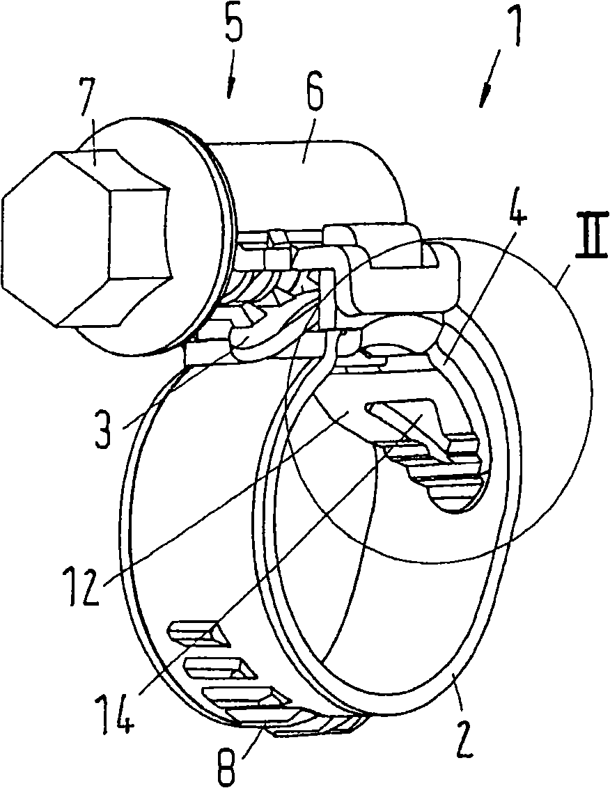
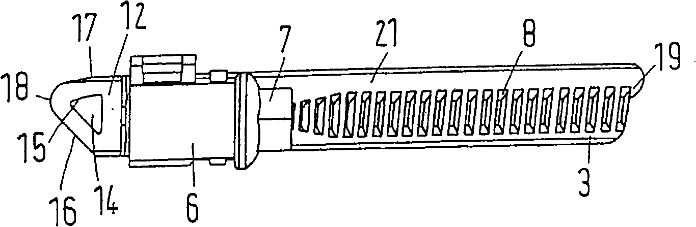
[0035]The worm screw clamping device 1 has a clamping band 2 which in turn has ends 3 and 4 . The two ends 3 and 4 are arranged overlapping such that a radially outer end 3 and a radially inner end 4 can be formed. The clamping band 2 is bent in an approximately circular manner so that substantially a c...


PUM


Abstract

The invention discloses a worm thread clamp and a method of forming worm thread clamp. The worm thread clamp includes a tension strap having end sections arranged to overlap in a circumferential direction to form a radially inner end section and a radially outer end section, a housing connected to the radially inner end section, and a tension screw arranged in the housing to engage thread elements on the radially outer end section. The radially inner end section is arranged to project from the housing in the circumferential direction and includes a bridge, and a weakening area is enclosed in the bridge.

Description

technical field [0001] The invention relates to a worm thread clamping device (Schneckengewindeschelle), with a clamping band (Spannband) (the clamping band again has ends overlapping each other in the circumferential direction), connected to a radially inner end The upper housing and the clamping screw arranged in the housing. The helix engages the threaded element on the radially outer end, while the radially inner end protrudes circumferentially onto the housing with the bridge. Background technique [0002] A worm thread clamping device of this type is known, for example, from German Patent No. DE19633435C1. [0003] The housing of the worm screw clamp should end flush with the clamping band radially on the inside, so that the components connected by means of the worm screw clamp (such as hoses) are as uniform as possible over the entire circumference. subjected to pressure loads. The housing therefore usually has a clamping rib arranged radially inside the radially i...

Claims


Application Information

Patent Timeline
Patent Type & Authority Applications(China)
IPC IPC(8): F16L33/08
CPCF16L33/08Y10T24/1427Y10T24/10Y10T24/1435Y10T24/1441
Inventor J·沃克M·克劳斯
Owner NORMA GERMANY GMBH
Why Eureka
Try Eureka