
Barrel type handle lock

A handle lock and cylinder type technology, applied in the field of handle locks, can solve the problems of complex structure, inconvenient installation and adjustment, large handle volume, etc. Effect

Active Publication Date: 2009-07-22
李宝强
View PDF6 Cites 5 Cited by
  • Summary
  • Abstract
  • Description
  • Claims
  • Application Information

AI Technical Summary

Problems solved by technology

[0002] In the prior art, the volume of the handle of the handle lock is usually large, so it will swing down under its own weight, so that the handle cannot be kept horizontal and affects the normal use of the handle lock
However, the current handle lock with handle return spring has also affected everyone's use due to its complex structure and inconvenient installation and adjustment.

Method used


Image

  • Barrel type handle lock
  • Barrel type handle lock
  • Barrel type handle lock

Examples


Embodiment Construction

[0015] Specific embodiments of the lock according to the present invention will be described in more detail below with reference to the accompanying drawings.

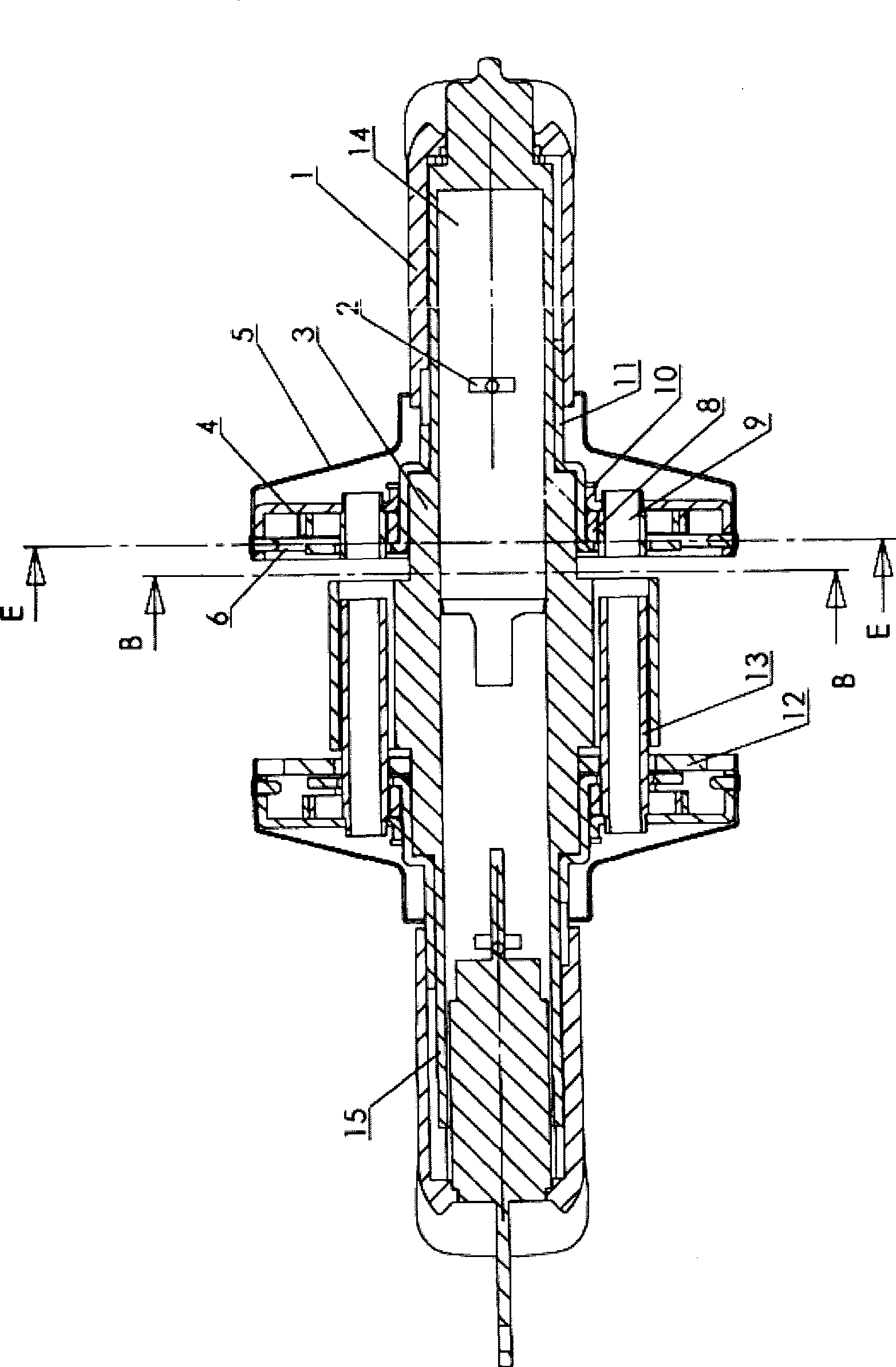
[0016] Specifically, the present invention improves the handle lock cover assembly on the basis of the handle lock. The handle lock includes a front pass 15 and a rear pass 14 , as well as a front cover assembly and a rear cover assembly, and the front cover assembly and the rear cover assembly are fixedly installed through studs 13 .

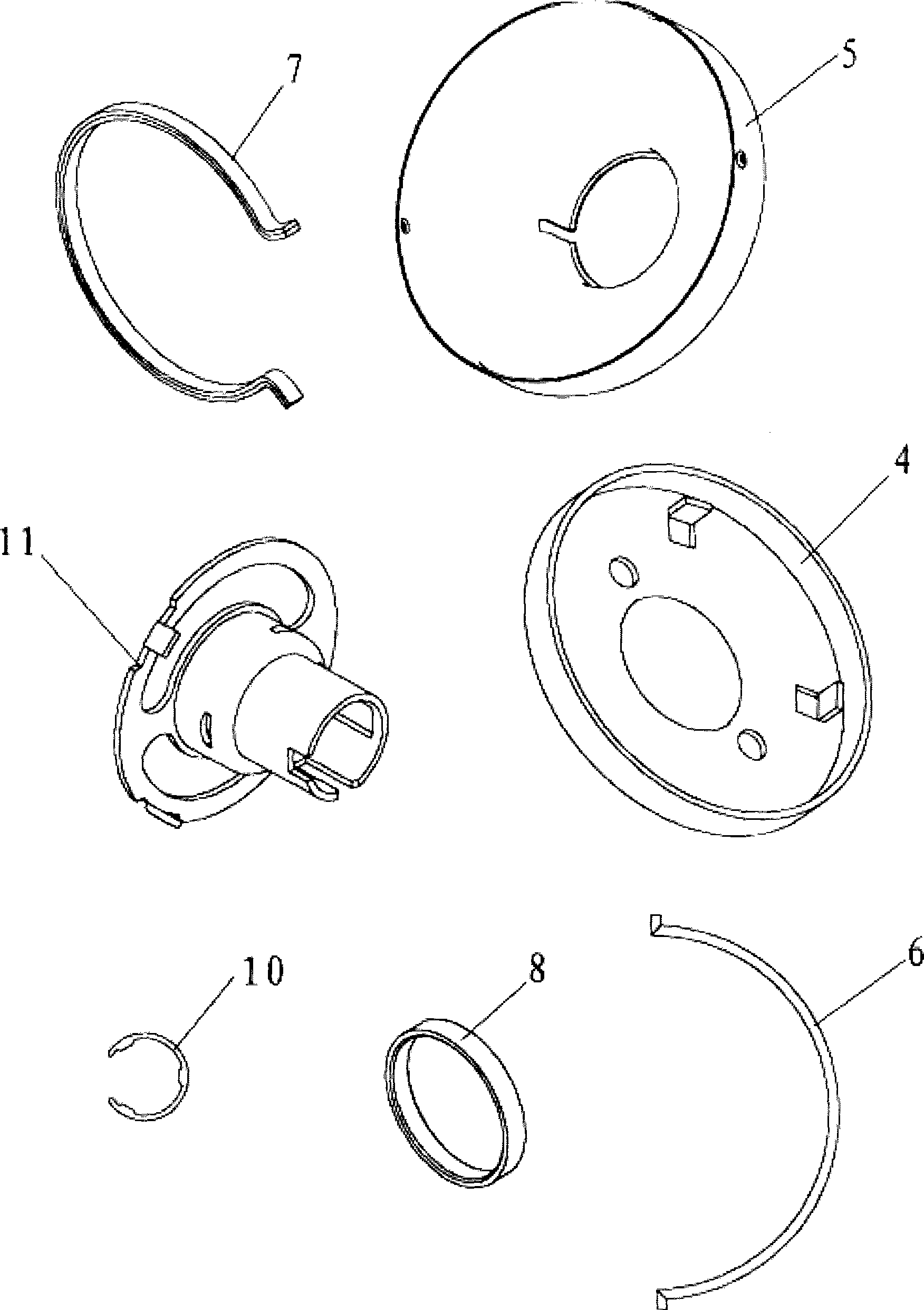
[0017] From figure 1 and figure 2 It can be seen that the rear cover assembly includes a turret 11 set on the lock body 3, a decorative cover 5 set on the turret 11, a cover 4 set on the outside of the turret 11 and inside the decorative cover 5, and a cover 4 located on the cover 4. The positioning spring 6 installed on the lower part of the decorative cover 5 in an engaging manner, the return spring 7 arranged inside the cover 4, the limit sleeve 8 set on the outside of the turret ...


PUM


Abstract

The invention relates to a cylinder handle lock, which comprises a lock body, a handle and a block cover component which comprises a front block cover component and a back block cover component. The back block cover component comprises a rotational frame which is sheathed on the lock body, a decorative cover which is sheathed on the rotational frame, a block cover which is sheathed outside the rotational frame and inside the decorative cover, a positioning spring which is arranged at the lower part of the block cover and is arranged on the decorative cover in a block way, a reset spring which is arranged inside the block cover and at the upper part of the positioning spring, a limiting sleeve which is sheathed outside the rotational frame, limiting columns which are arranged at the two sides of the limiting sleeve symmetrically and a block spring which is sheathed on the rotational frame and above the limiting sleeve. The application range of the handle lock is comparatively wide for door frames of different thicknesses, assembly and disassembly are convenient, and the use function of the lock cannot be affected when the lock endures larger torque.

Description

technical field [0001] The invention relates to a handle lock, in particular to a handle lock with a handle reset structure. Background technique [0002] In the prior art, the volume of the handle of the handle lock is usually relatively large, so that it will swing down under its own weight, so that the handle cannot be kept horizontal, and affects the normal use of the handle lock. But the handle lock with the handle back-moving spring has also affected everyone's use due to complex structure and inconvenient installation and adjustment at present. In addition, users have other requirements for handle locks, for example, a handle lock with a larger adjustment range is required for door frames of different thicknesses, and the use function of the lock needs to be maintained when subjected to a large torque. Contents of the invention [0003] Therefore, the object of the present invention is to provide a cylinder handle lock, which adopts simpler components and a flexibl...

Claims


Application Information

Patent Timeline
Patent Type & Authority Applications(China)
IPC IPC(8): E05B63/00E05B3/00E05B9/06
Inventor 李宝强
Owner 李宝强
Learn More