
Method and device for constructing solid waste landfill yard with group silos

A landfill and population technology, applied in the direction of solid waste removal, etc., can solve the problems of complex composition, difficult treatment process, and high pollution concentration of leachate

Inactive Publication Date: 2009-07-22
庄维健
View PDF0 Cites 3 Cited by
  • Summary
  • Abstract
  • Description
  • Claims
  • Application Information

AI Technical Summary

Problems solved by technology

[0002] Because the existing landfills cannot effectively isolate rainwater and surface runoff water, a large amount of leachate will be produced. The leachate pollution concentration is high and the composition is complex. Its treatment process has always been the biggest technical problem.
[0003] The existing tailings have a high water content when they enter the warehouse. Although some water can be discharged through the water filtration facilities after entering the warehouse, they are often supplemented by rainwater and surface runoff water. In the saturated state, a large lateral pressure will be formed on the tailings dam. Once the dam collapses, it will form a man-made debris flow and cause great harm to the downstream.

Method used


Image

  • Method and device for constructing solid waste landfill yard with group silos
  • Method and device for constructing solid waste landfill yard with group silos
  • Method and device for constructing solid waste landfill yard with group silos

Examples


Embodiment Construction

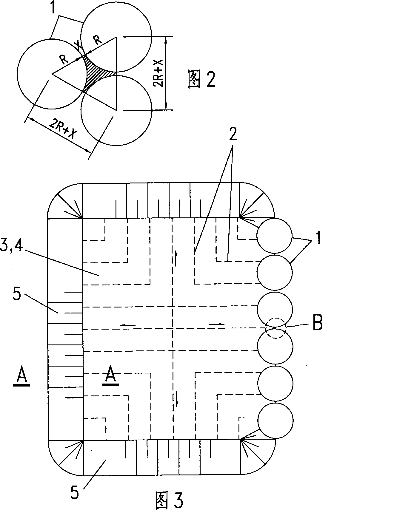
[0048] The following two examples of building solid waste landfills on plains are used to describe the specific implementation methods of solid waste as garbage or solid waste as tailings.

[0049] One, embodiment 1 (solid waste is rubbish 6):

[0050] 1. Design information:

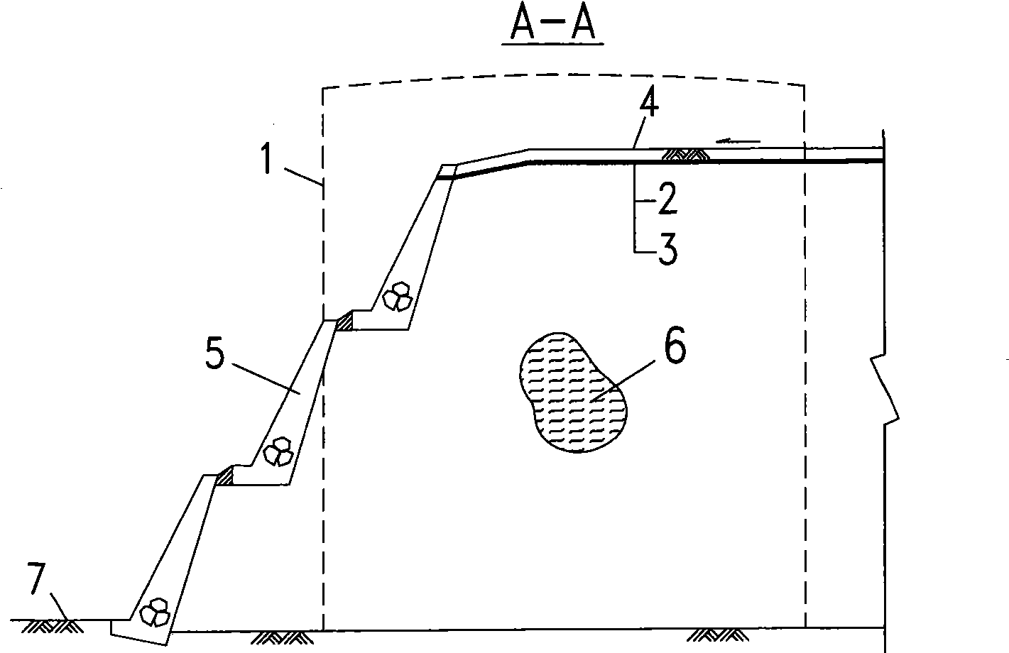
[0051] The diameter of the designed silo is 20 meters, and the average height after filling is 22 meters, so the volume of a single silo is 6911 cubic meters. Based on 460 cubic meters of garbage per day, it takes 15 days (half a month) to fill one silo, and 24 silos can be filled in one year. If the design life of the landfill is 20 years, then a total of 24×20=480 silos need to be built, and the total amount of landfill is: 6911×480=3317280 cubic meters (ie 3.317 million cubic meters).

[0052] If 24 silos are arranged in every row, a total of 20 rows are arranged, and the center line of each adjacent silo is distributed in an equilateral triangle at 21 meters, as shown in Figure 2, R=10 meters; X=1 ...


PUM


Abstract

The invention discloses a method and a device for constructing a solid waste landfill site by group silos, and belongs to the technical field of solid waste treatment engineering. Large amount of leachate generated by the prior refuse landfill site becomes a technical problem difficult to solve, the method and the device can effectively block surface runoff and rainwater invasion, so that the refuse landfill site does not generate overflow leachate, and the technical problem is solved. When the prior tailing reservoir is subjected to long-time rainfall, the tailing in the reservoir is liquid and generates large lateral pressure to a tailing dam; and once the dam collapses, artificial debris flow is formed to cause huge damage to the downstream. Besides effectively blocking the surface runoff and the rainwater invasion, the method and the device can also continuously discharge accumulated water in the tailing for a long time to form solid; and a tailing drying landfill site is finally formed to thoroughly eliminate dam collapse hidden danger. The method and the device have particularly important significance that the method and the device are applied to widening and covering the established refuse landfill site (or the tailing reservoir), not only can eliminate safety hidden danger of the prior dam body, but also can utilize the prior site to increase large reservoir capacity.

Description

technical field [0001] The solid waste in the present invention mainly refers to garbage and tailings, and relates to the technical field of solid waste treatment engineering. Background technique [0002] Because existing landfills cannot effectively isolate rainwater and surface runoff water, a large amount of leachate will be produced. The leachate pollution concentration is high and the composition is complex. Its treatment process has always been the biggest technical problem. [0003] The existing tailings have a high water content when they enter the warehouse. Although some water can be discharged through the water filtration facilities after entering the warehouse, they are often supplemented by rainwater and surface runoff water. In the saturated state, a large lateral pressure will be formed on the tailings dam. Once the dam collapses, an artificial debris flow will be formed and cause great harm to the downstream. Contents of the invention [0004] The present...

Claims


Application Information

Patent Timeline
Patent Type & Authority Applications(China)
IPC IPC(8): B09B5/00
Inventor 庄维健
Owner 庄维健
Learn More