Electronic clock
A technology of electronic clocks and rotors, applied in the direction of electromechanical clocks, clocks, electrical components, etc., can solve the problems of time delay, fatal electronic clocks, etc., and achieve the effect of increasing the degree of freedom
- Summary
- Abstract
- Description
- Claims
- Application Information
AI Technical Summary
Problems solved by technology
Method used
Image


Examples
Embodiment 1
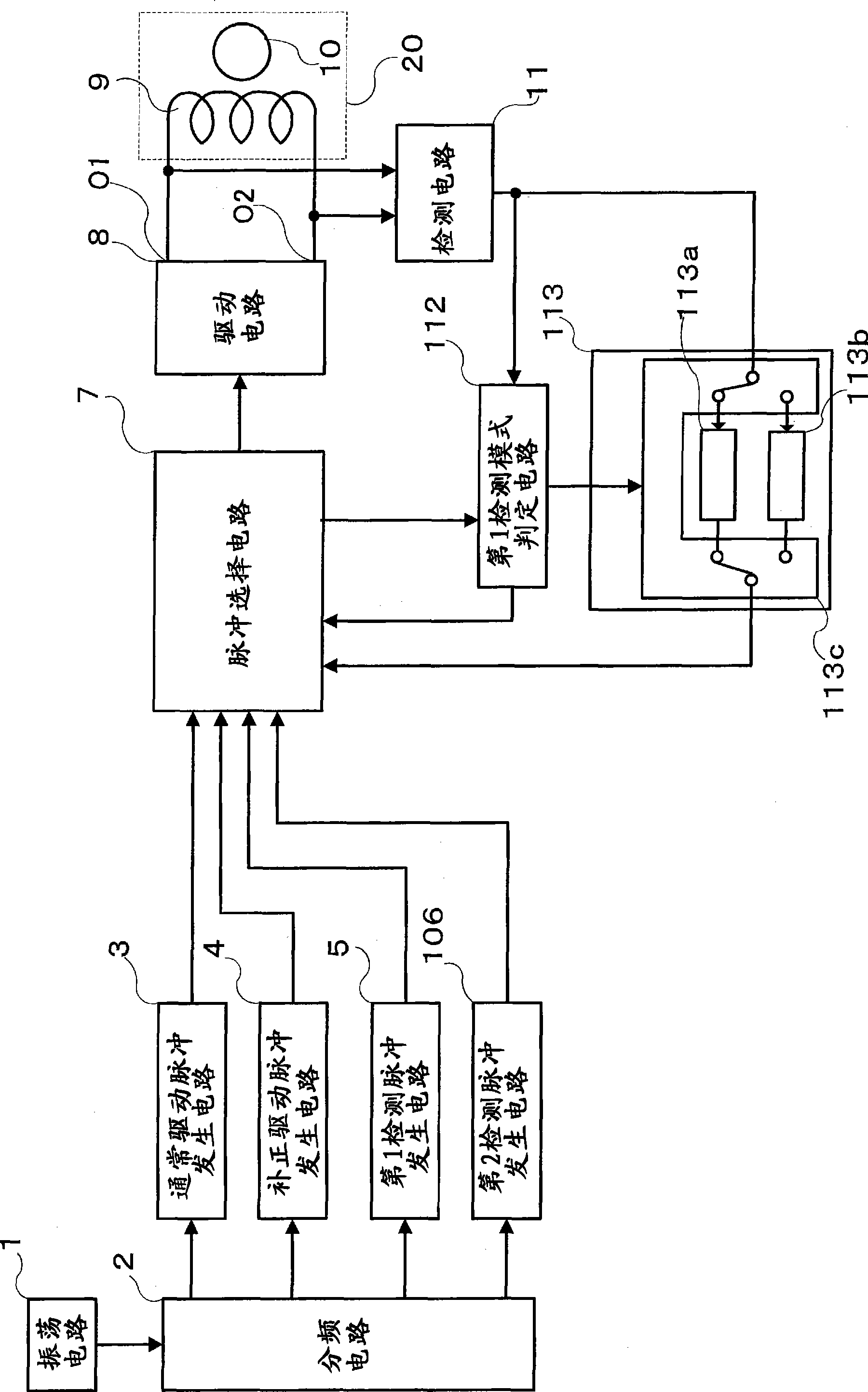
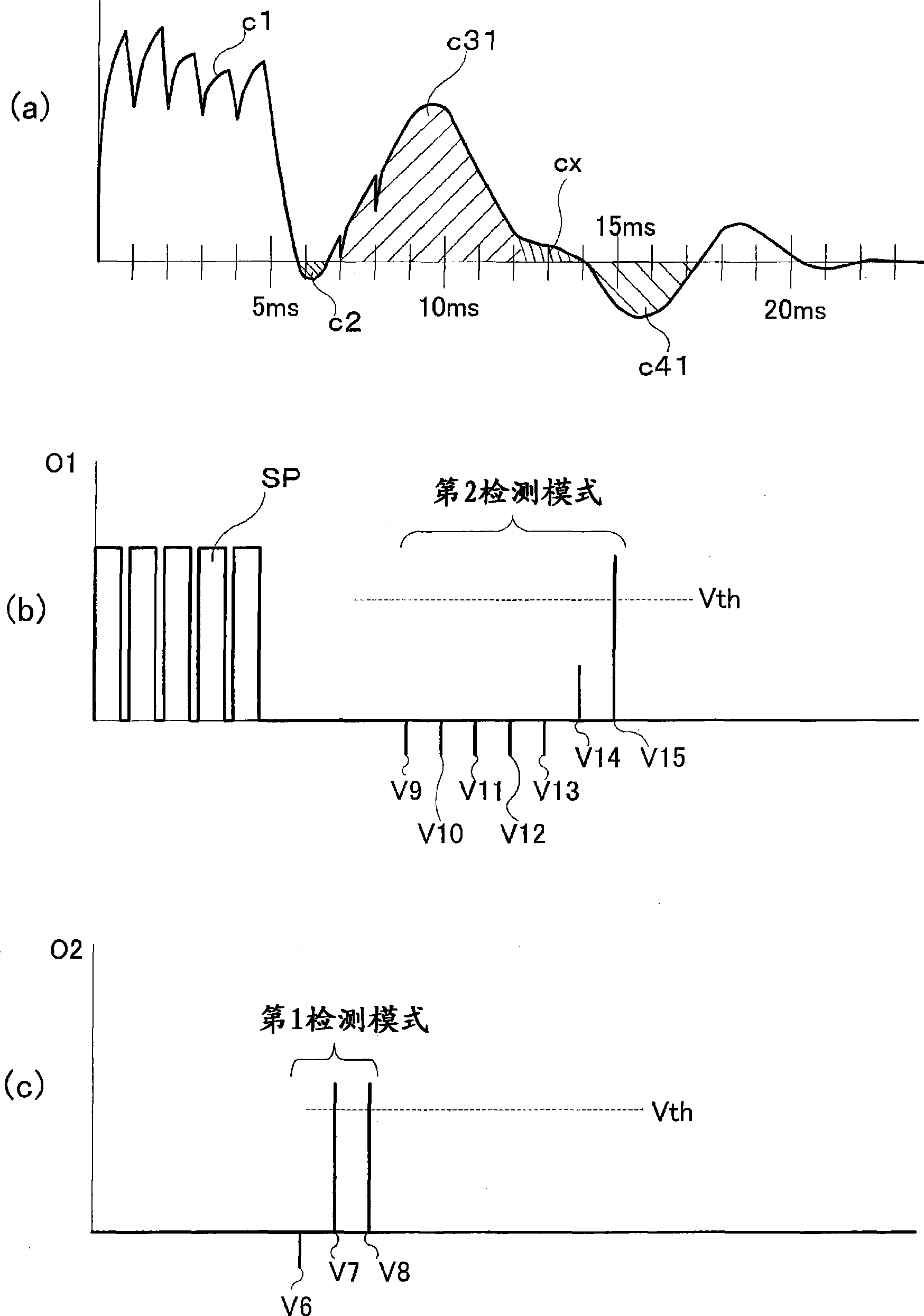
[0089] Next, Embodiment 1 of the present invention will be described in detail with reference to the drawings. Embodiment 1 is an example in which the maximum number of detection signals in the second detection mode is changed based on the determination time for determining the presence or absence of the detection signal in the first detection mode, and the determination period of the detection signal is changed. figure 1 is a block diagram showing the circuit configuration of the electronic clock of Embodiment 1, figure 2 It is a pulse waveform diagram generated by the circuit of the electronic clock of embodiment 1, image 3 It is a current waveform and a voltage waveform diagram that occur in the winding when a needle with a large moment of inertia is installed on the electronic clock of Example 1, Figure 4 It is an example of a current waveform and a voltage waveform diagram when the rotor of the electronic clock of the first embodiment is unable to rotate due to a dec...
Embodiment 2
[0110] Next, Embodiment 2 of the present invention will be described in detail with reference to the drawings. Embodiment 2 is an example in which the detection pulse period in the second detection mode is changed and the detection signal determination period is changed based on the determination period for determining the presence or absence of a detection signal in the first detection mode. Figure 8 is a block diagram showing the circuit configuration of the electronic clock of the second embodiment, Figure 9 It is the pulse waveform diagram that the circuit of the electronic clock of embodiment 2 takes place, image 3 It is a current waveform and a voltage waveform diagram (the same drawing as that of Embodiment 1) that occurs in the winding when the electronic clock of Embodiment 2 is equipped with a large needle of moment of inertia, Figure 10 This is an example of a current waveform and a voltage waveform diagram generated in the winding when the rotor of the second ...
Embodiment 3
[0127] Next, Embodiment 3 of the present invention will be described in detail with reference to the drawings. Embodiment 3 is an example in which the period of the detection pulse is changed for some detection signals in the second detection mode according to the detection conditions in the first detection mode. Figure 12 is a block diagram showing the circuit configuration of the electronic clock of the third embodiment, Figure 13 It is the pulse waveform diagram of the circuit output of the electronic clock of embodiment 3, image 3 It is a current waveform and a voltage waveform diagram (the same drawings as in Embodiment 1) that occur in the winding when a needle with a large moment of inertia is installed in the electronic clock of Embodiment 3, Figure 14 It is a current waveform and a voltage waveform diagram when the rotor of the electronic clock of Example 3 cannot rotate. Components that are the same as those described in the conventional example or Embodiment 1...
PUM
 Abstract
Description
Claims
Application Information
 - R&D
- Intellectual Property
- Life Sciences
- Materials
- Tech Scout
- Unparalleled Data Quality
- Higher Quality Content
- 60% Fewer Hallucinations
Browse by: Latest US Patents, China's latest patents, Technical Efficacy Thesaurus, Application Domain, Technology Topic, Popular Technical Reports.
© 2025 PatSnap. All rights reserved.Legal|Privacy policy|Modern Slavery Act Transparency Statement|Sitemap|About US| Contact US: help@patsnap.com