
Combined circuit and electronic element

An electronic component and combined technology, applied in the direction of electrical components, circuits, electric solid devices, etc., can solve the problems of low power density, reduced power density, large volume, etc.

Active Publication Date: 2009-07-15
DELTA ELECTRONICS INC
View PDF0 Cites 15 Cited by
  • Summary
  • Abstract
  • Description
  • Claims
  • Application Information

AI Technical Summary

Problems solved by technology

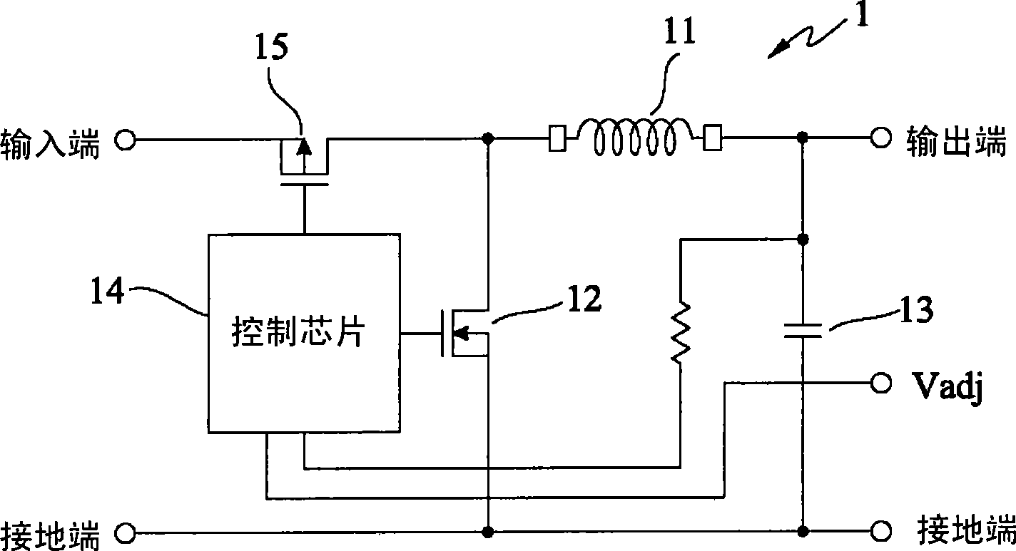
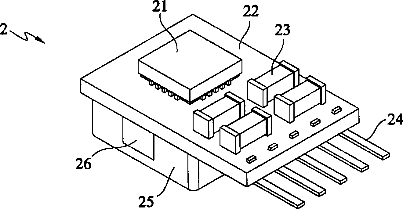
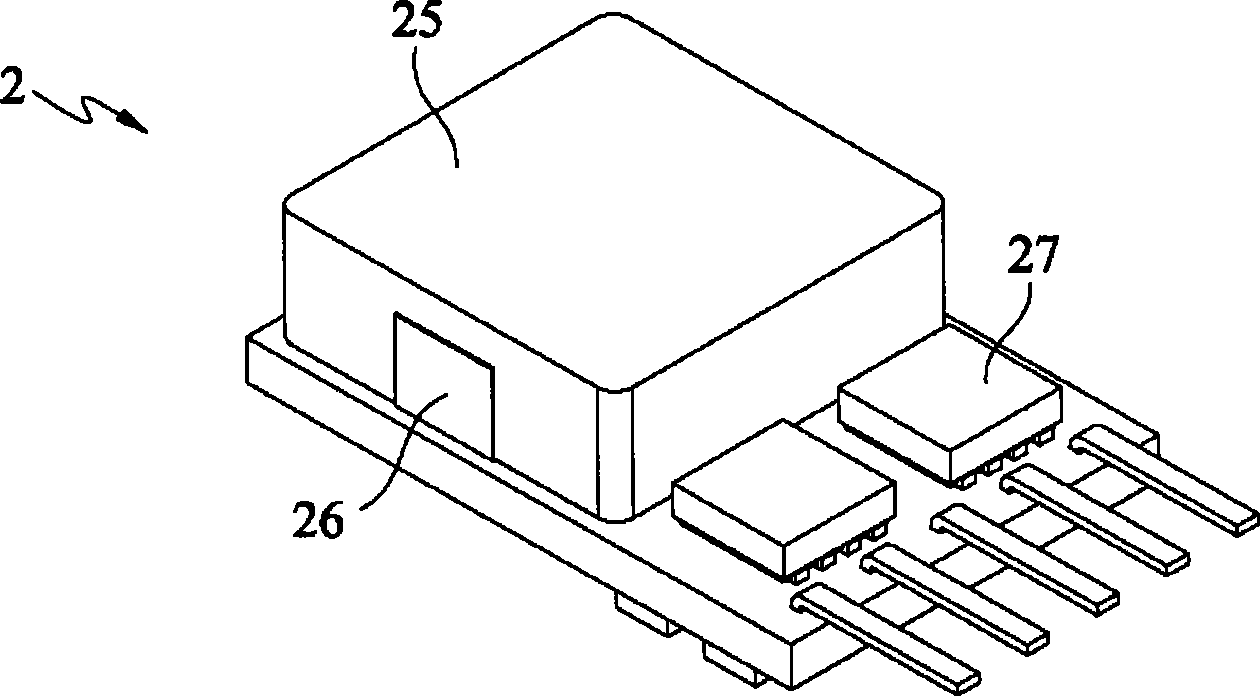
[0008] However, in addition to occupying a certain space on the circuit board 34, the wavy pin 33 itself has a certain height, which will increase the volume of the point-of-load DC converter 3 and reduce its power density.
[0009] To sum up, in the existing packaging methods, the point-of-load DC converters are limited by pins, making the overall volume larger and the power density lower

Method used


Image

  • Combined circuit and electronic element
  • Combined circuit and electronic element
  • Combined circuit and electronic element

Examples


Embodiment Construction

[0055] In order to effectively increase the power density of electronic devices (especially voltage converters) and reduce the overall size, the present invention proposes a new type of pin design, which is widely used in various common electronic devices. see Figure 4A , 4C and Figure 4B , 4D As shown, they respectively show a bottom view and a top view of an inductive element 62 in the first embodiment of the present invention. In more detail, the inductive element 62 can be an inductor. In actual application, the inductive element 62 can be a co-fired magnetic material inductor or a wire-wound pressure-fit inductor. It should be noted that the inductive element 62 in this embodiment is only for illustration, in fact, the technology disclosed in the present invention can be applied to the main body of general electronic elements, such as field effect transistors.

[0056] One of the features of the present invention is that the outer surface of the inductive element 62...


PUM


Abstract

The present invention discloses a combined circuit, which comprises an inductive element, a connecting prime conductor and a first electronic component, wherein the connecting prime conductor is used to clad a first surface of the inductive element; the first electronic component stacks with the inductive element mutually; the combined circuit is electronically connected to a carrier through connecting the prime conductor.

Description

technical field [0001] The present invention relates to an electronic component and a combined circuit using the component. More specifically, it relates to an electronic component and a combined circuit that can reduce the overall size of the electronic component to increase the power density of the overall power supply. Background technique [0002] General electrical appliances use AC power. After the AC power is converted into an array of DC power by an AC to DC converter (AC to DC converter), it can supply each electronic component inside the appliance to meet its different power requirements. However, due to the partial loss during power conversion, the conversion efficiency of converting to multiple sets of DC power output is not high. Therefore, if it is converted into a group of DC power first, and then converted into the DC power required by the array, the efficiency can be greatly improved. In addition, portable electronic products use a DC power source (ie, a ba...

Claims


Application Information

Patent Timeline
Patent Type & Authority Applications(China)
IPC IPC(8): H02M1/00H05K7/02H01L25/00H01L23/48H01F27/28
CPCH01L2224/16225H01L2924/13091H01L2924/19105
Inventor 曾剑鸿杨威洪守玉应建平
Owner DELTA ELECTRONICS INC
Learn More