
Water segregator of water tap

A water divider and faucet technology, which is applied in the direction of valve details, multi-way valves, engine components, etc., can solve the problems of user's increased operating force, difficult operation, and limited reduction, so as to reduce the lifting resistance and apply Wide range and good sealing effect

Inactive Publication Date: 2009-07-15
YUHUAN KINGJOY METAL PROD
View PDF0 Cites 4 Cited by
  • Summary
  • Abstract
  • Description
  • Claims
  • Application Information

AI Technical Summary

Problems solved by technology

[0004] In order to reduce the lift and pressure, people reduce the force-bearing area of ​​the seal on the push-pull rod to save labor in use, but the degree of reduction is very limited, because too small force-bearing area of ​​the seal will affect the flow and water separation of the faucet. Effect
[0005] Therefore, the technical principle of the existing faucet diverter determines the contradiction between the reliability of its water diversion function and the labor-saving use, especially under low pressure, although the switch is not laborious, the water diversion function will appear unreliable
When the water pressure is high, since the positive pressure force of the water will increase with the increase of the water pressure, the water separation function will be reliable, but the user's operating force will increase accordingly, and even cause difficult operation in severe cases.

Method used


Image

  • Water segregator of water tap
  • Water segregator of water tap
  • Water segregator of water tap

Examples


Embodiment Construction

[0024] The following are specific embodiments of the present invention and in conjunction with the accompanying drawings, the technical solutions of the present invention are further described, but the present invention is not limited to these embodiments.

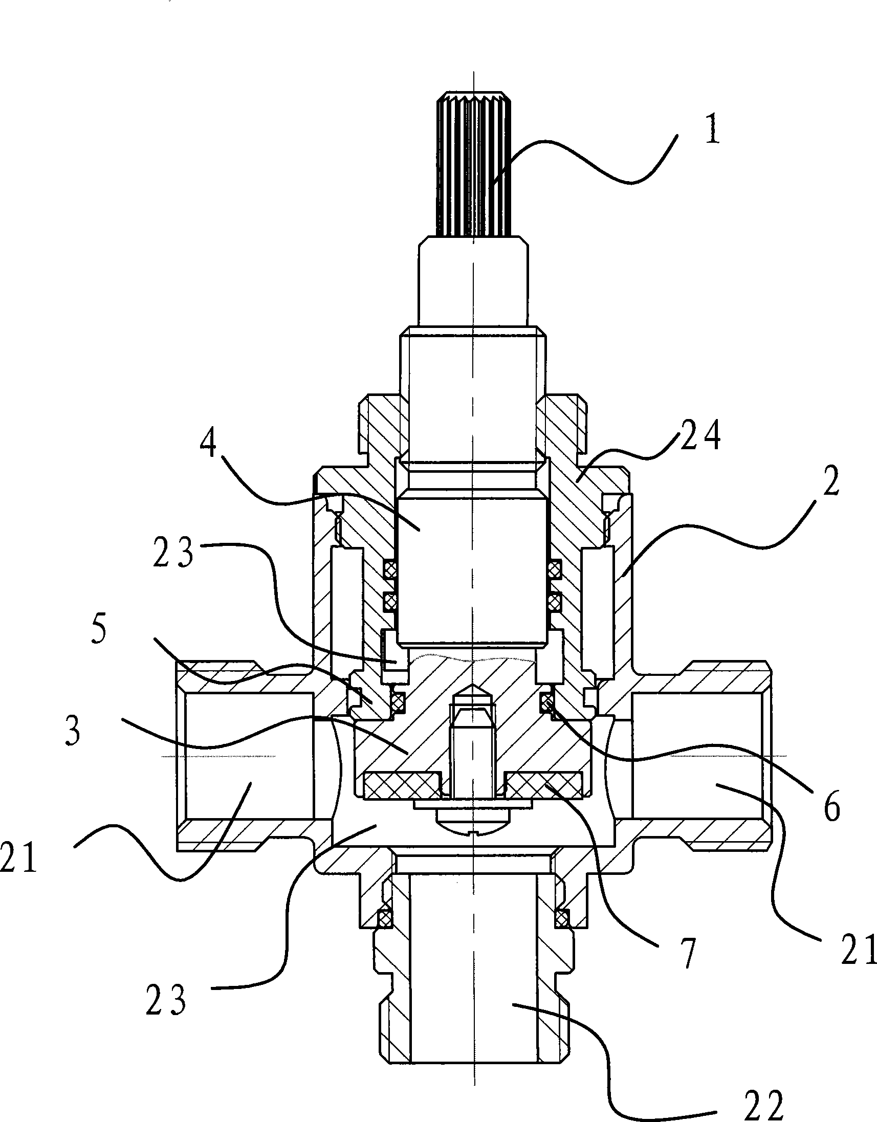
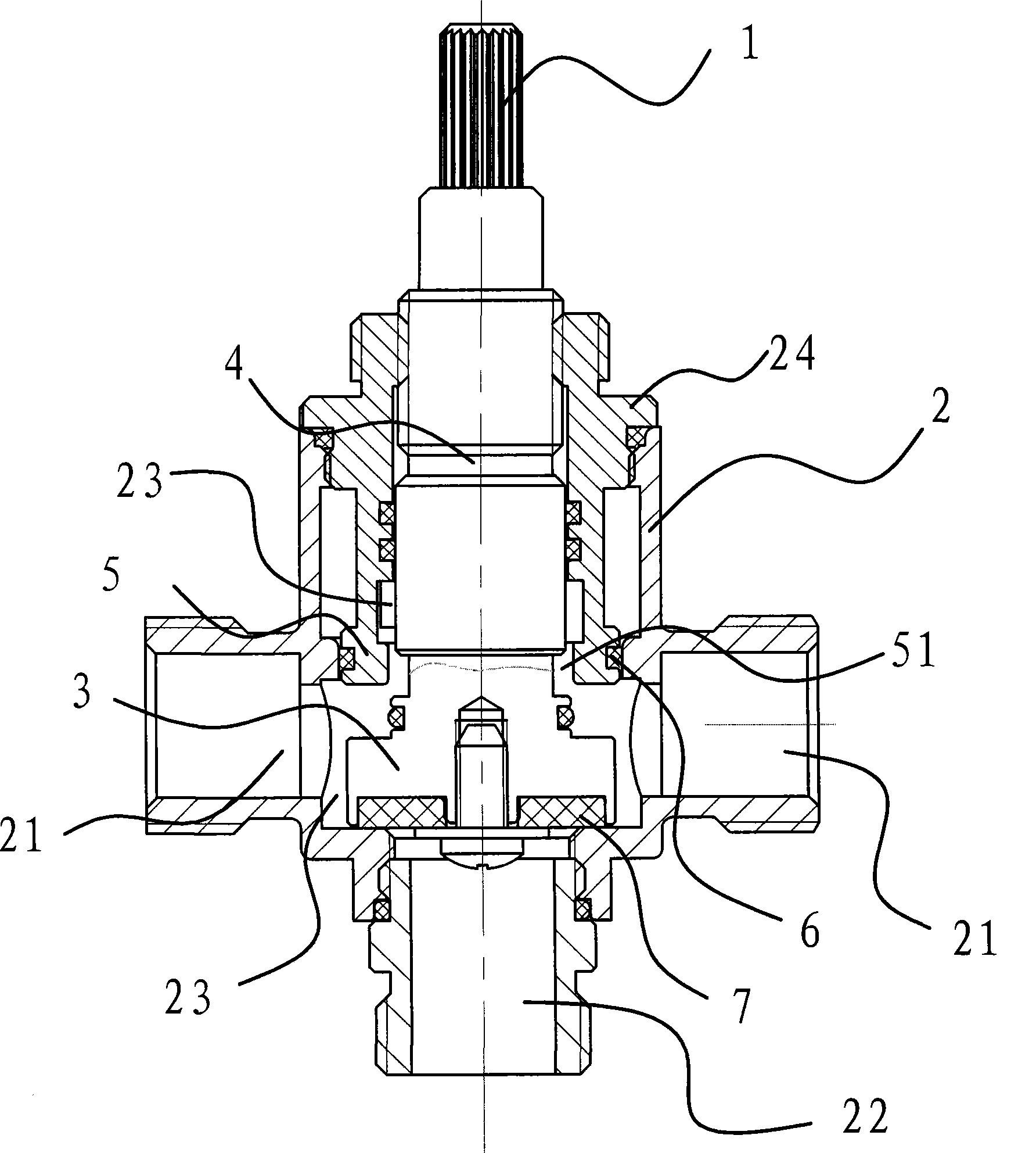
[0025] Such as figure 1 , figure 2 , image 3 and Figure 4 As shown, the water distributor of this faucet includes a hand wheel 1, a valve body 2, a valve core 3, a valve stem 4 and a valve core seat 5, so that the water entering the water inlet pipe 21 can be transferred from one outlet pipe 22 or another Root outlet pipe 22 goes out.

[0026] Specifically, the valve body 2 has two water inlet pipes 21 and two water outlet pipes 22, the valve core 3 and the valve stem 4 are arranged in the valve body 2, one end of the valve stem 4 is fixedly connected with the valve core 3, and the other end is passed through The outlet valve body 2 is fixedly connected with the handwheel 1. There are two cavities 23 in the valve bo...


PUM


Abstract

The invention belongs to the technical field of valve and relates to a water separator of a tap which solves the technical defects of unfirm sealing when the water pressure in the inner cavity of a water separator is low as well as non labor saving when the water pressure is high in the prior art. The water separator of the tap comprises a handwheel, a valve body with an inlet tube and two outflow tubes, as well as a valve core and a valve rod arranged in the valve body; the middle of the valve rod is connected with the valve core in a screwing way; one end of the valve rod penetrates the valve body and is fixedly connected with the handwheel; an upper empty cavity and a lower empty cavity are arranged in the valve body, respectively connected with one outflow tube, and are connected by a through hole; the inlet tube is connected with one of the empty cavities; the valve core is arranged in the empty cavity connected with the inlet tube; the valve core is fixedly connected with the valve rod; and the bottom surface of the valve core is provided with a sealing element capable of sealing the outflow tube connected with the empty cavity; the top surface of the valve core is provided with a sealing element capable of sealing the through hole. The water separator has good leak tightness and can use the assistance of water flow to reduce the drive force of the valve rod. The water separator is reasonably designed, has simple structure, saves labor, and is convenient to be operated.

Description

technical field [0001] The invention belongs to the technical field of valves and relates to a water distributor for a faucet. Background technique [0002] At present, the water separator of the existing faucet utilizes the pressure of water to realize water diversion. An axially movable push-pull rod is installed in the center of the water seat inside the water diverter of the faucet, and a sealing member is fixed on the push-pull rod. The axial movement opens and closes the water inlets of the two flow channels at the water outlet end of the faucet that need to be divided, so as to realize the function of dividing water. In order to make the water separation function reliable, especially the water separation function under low pressure, the seal must have a certain pressure-bearing section to ensure sufficient sealing pressure under low pressure. However, when the water pressure is high, the driving force of the push-pull rod will also vary The rise of the water pressure...

Claims


Application Information

Patent Timeline
Patent Type & Authority Applications(China)
IPC IPC(8): F16K11/044F16K27/00F16K27/12
Inventor 盛建肖黄友波
Owner YUHUAN KINGJOY METAL PROD
Learn More